


3. SIGNALS AND WIRING
3 - 26
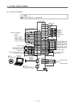
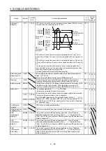
The servo amplifier front view shown is that of the MR-J4-20A-RJ or less. Refer to chapter 9 DIMENSIONS
for the appearances and connector layouts of the other servo amplifiers.
2
LG
3
MO2
1
MO1
CN6
CN1
4
MRR
2
LG
8
6
1
P5
5
10
3
MR
7
9
BAT
(Note 2) CN2
MXR
MX
2
4
6
8
10
12
14
16
18
20
22
24
1
3
5
7
9
11
13
15
17
19
21
23
27
29
31
33
35
37
39
41
43
45
47
49
26
28
30
32
34
36
38
40
42
44
46
48
25
50
4
MRR2
2
LG
8
6
1
P5
5
10
3
MR2
7
9
(Note 1, 2) CN2L
(For using serial encoder)
MXR2
THM2
THM1
MX2
4
PAR
2
LG
8
6
1
P5
PBR
PSEL
PB
5
10
3
PA
7
9
(Note 1, 2) CN2L
(for using A/B/Z-phase pulse encoder)
PZR
PZ
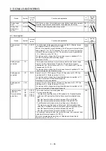
The frames of the CN1 connectors
are connected to the protective earth
terminal in the servo amplifier.
CN5 (USB connector)
refer to section 11.7.
CN3 (RS-422 connector)
refer to chapter 14.
The 3M make connector is shown.
CN8
For the STO I/O signal connector,
refer to section 11.13.
(Battery connector)
refer to section 11.8.
CN4
BAT
Note 1. The MR-J4-_A_-RJ servo amplifiers have CN2L connectors. This CN2L is a connector of 3M.
When using any other connector, refer to each servo motor instruction manual.
2. Refer to table 1.1 for connections of external encoders.
The device assignment of the CN1 connector pins changes depending on the control mode. For the pins
which are given parameters in the related parameter column, their devices will be changed using those
parameters.
Summary of Contents for MR-J4-100A
Page 9: ...A 8 MEMO ...
Page 61: ...1 FUNCTIONS AND CONFIGURATION 1 44 MEMO ...
Page 67: ...2 INSTALLATION 2 6 MEMO ...
Page 137: ...3 SIGNALS AND WIRING 3 70 MEMO ...
Page 261: ...6 NORMAL GAIN ADJUSTMENT 6 24 MEMO ...
Page 291: ...7 SPECIAL ADJUSTMENT FUNCTIONS 7 30 MEMO ...
Page 299: ...8 TROUBLESHOOTING 8 8 MEMO ...
Page 319: ...9 OUTLINE DRAWINGS 9 20 MEMO ...
Page 461: ...12 ABSOLUTE POSITION DETECTION SYSTEM 12 36 MEMO ...
Page 511: ...14 COMMUNICATION FUNCTION 14 38 MEMO ...
Page 559: ...16 USING A DIRECT DRIVE MOTOR 16 20 MEMO ...
Page 583: ...17 FULLY CLOSED LOOP SYSTEM 17 24 MEMO ...
Page 621: ...APPENDIX App 38 ...
Page 639: ......