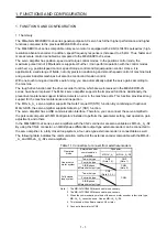


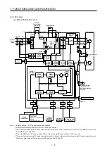


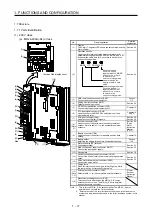


1. FUNCTIONS AND CONFIGURATION
1 - 15
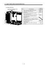
Function Description
Detailed
explanation
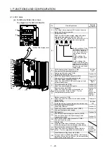
Output signal selection
(device settings)
The output devices including MBR (Electromagnetic brake interlock) can be assigned
to certain pins of the CN1 connector.
[Pr. PD23] to
[Pr. PD28]
Output signal (DO) forced
output
Output signal can be forced on/off independently of the servo status.
Use this function for checking output signal wiring, etc.
Section 4.5.8
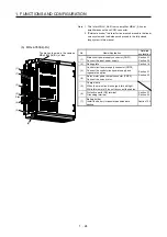
Restart after instantaneous
power failure
If the input power supply voltage had reduced to cause an alarm but has returned to
normal, the servo motor can be restarted by merely switching on the start signal.
(available in the future)
Command pulse selection
Command pulse train form can be selected from among three different types.
[Pr. PA13]
Torque limit
Servo motor torque can be limited to any value.
Section 3.6.1
(5)
[Pr. PA11]
[Pr. PA12]
Speed limit
Servo motor speed can be limited to any value.
Section 3.6.3
(3)
[Pr. PC05] to
[Pr. PC11]
Status display
Servo status is shown on the 5-digit, 7-segment LED display
Section 4.5
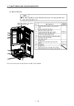
External I/O signal display
On/off statuses of external I/O signals are shown on the display.
Section 4.5.7
Automatic VC offset
Voltage is automatically offset to stop the servo motor if it does not come to a stop
when VC (Analog speed command) or VLA (Analog speed limit is 0 V.
Section 4.5.4
Alarm code output
If an alarm has occurred, the corresponding alarm number is outputted in 3-bit code.
Chapter 8
Test operation mode
Jog operation, positioning operation, motor-less operation, DO forced output, and
program operation
MR Configurator2 is required to perform positioning operation or program operation.
Section 4.5.9
Analog monitor output
Servo status is output in terms of voltage in real time.
[Pr. PC14],
[Pr. PC15]
MR Configurator2
Using a personal computer, you can perform the parameter setting, test operation,
monitoring, and others.
Section 11.7
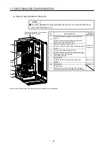
Linear servo system
Linear servo system can be configured using a linear servo motor and liner encoder.
This is used with servo amplifiers with software version A5 or later. Check the
software version of the servo amplifier using MR Configurator2.
Chapter 15
Direct drive
servo system
The direct drive servo system can be configured to drive a direct drive motor.
This is used with servo amplifiers with software version A5 or later. Check the
software version of the servo amplifier using MR Configurator2.
Chapter 16
Fully closed loop system
Fully closed loop system can be configured using the load-side encoder.
This is used with servo amplifiers with software version A5 or later. Check the
software version of the servo amplifier using MR Configurator2.
Chapter 17
One-touch tuning
Gain adjustment is performed just by one click on a certain button on MR
Configurator2 or operation section.
Section 6.1
Tough drive function
This function makes the equipment continue operating even under the condition that
an alarm occurs.
The tough drive function includes two types: the vibration tough drive and the
instantaneous power failure tough drive.
Section 7.3
Drive recorder function
This function continuously monitors the servo status and records the status transition
before and after an alarm for a fixed period of time. You can check the recorded data
on the drive recorder window on MR Configurator2 by clicking the "Graph" button.
However, the drive recorder will not operate on the following conditions.
1. You are using the graph function of MR Configurator2.
2. You are using the machine analyzer function.
3. [Pr. PF21] is set to "-1".
[Pr. PA23]
STO function
This function is a functional safety that complies with IEC/EN 61800-5-2. You can
create a safety system for the equipment easily.
Chapter 13
Servo amplifier life diagnosis
function
You can check the cumulative energization time and the number of on/off times of the
inrush relay. This function gives an indication of the replacement time for parts of the
servo amplifier including a capacitor and a relay before they malfunction.
MR Configurator2 is necessary for this function.
Power monitoring function
This function calculates the power running energy and the regenerative power from
the data in the servo amplifier such as speed and current. Power consumption and
others are displayed on MR Configurator2.
Machine diagnosis function
From the data in the servo amplifier, this function estimates the friction and vibrational
component of the drive system in the equipment and recognizes an error in the
machine parts, including a ball screw and bearing.
MR Configurator2 is necessary for this function.
Summary of Contents for MR-J4-100A
Page 9: ...A 8 MEMO ...
Page 61: ...1 FUNCTIONS AND CONFIGURATION 1 44 MEMO ...
Page 67: ...2 INSTALLATION 2 6 MEMO ...
Page 137: ...3 SIGNALS AND WIRING 3 70 MEMO ...
Page 261: ...6 NORMAL GAIN ADJUSTMENT 6 24 MEMO ...
Page 291: ...7 SPECIAL ADJUSTMENT FUNCTIONS 7 30 MEMO ...
Page 299: ...8 TROUBLESHOOTING 8 8 MEMO ...
Page 319: ...9 OUTLINE DRAWINGS 9 20 MEMO ...
Page 461: ...12 ABSOLUTE POSITION DETECTION SYSTEM 12 36 MEMO ...
Page 511: ...14 COMMUNICATION FUNCTION 14 38 MEMO ...
Page 559: ...16 USING A DIRECT DRIVE MOTOR 16 20 MEMO ...
Page 583: ...17 FULLY CLOSED LOOP SYSTEM 17 24 MEMO ...
Page 621: ...APPENDIX App 38 ...
Page 639: ......