


3. SIGNALS AND WIRING
3 - 50
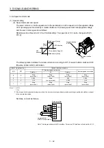
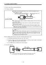
Normally, connect as follows.
Japan resistor
RRS10 or equivalent
DICOM
P15R
VLA
LG
SD
Servo amplifier
SP1
(Note)
2 k
Ω
2 k
Ω
24 V DC
Note. This diagram shows sink I/O interface. For source I/O interface, refer to section 3.9.3.
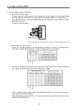
(b) Speed limit value selection
Select any of the speed settings by the internal speed limit 1 and by VLA (Analog speed limit) using
SP1 (Speed selection 1) as follows.
(Note) Input device
SP1
Speed command value
0
VLA (Analog speed limit)
1
Pr. PC05 Internal speed limit 1
Note. 0: Off
1: On
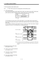
You can change the speed during rotation. To accelerate/decelerate, set acceleration/deceleration
time constant in [Pr. PC01] or [Pr. PC02].
When the internal speed command 1 is used to command a speed, the speed does not vary with the
ambient temperature.
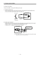
(c) VLC (Limiting speed)
As in section 3.6.3 (3) (c)
(5) Torque control in torque control mode
As in section 3.6.3 (1)
(6) Torque limit in torque control mode
As in section 3.6.3 (2)
Summary of Contents for MR-J4-100A
Page 9: ...A 8 MEMO ...
Page 61: ...1 FUNCTIONS AND CONFIGURATION 1 44 MEMO ...
Page 67: ...2 INSTALLATION 2 6 MEMO ...
Page 137: ...3 SIGNALS AND WIRING 3 70 MEMO ...
Page 261: ...6 NORMAL GAIN ADJUSTMENT 6 24 MEMO ...
Page 291: ...7 SPECIAL ADJUSTMENT FUNCTIONS 7 30 MEMO ...
Page 299: ...8 TROUBLESHOOTING 8 8 MEMO ...
Page 319: ...9 OUTLINE DRAWINGS 9 20 MEMO ...
Page 461: ...12 ABSOLUTE POSITION DETECTION SYSTEM 12 36 MEMO ...
Page 511: ...14 COMMUNICATION FUNCTION 14 38 MEMO ...
Page 559: ...16 USING A DIRECT DRIVE MOTOR 16 20 MEMO ...
Page 583: ...17 FULLY CLOSED LOOP SYSTEM 17 24 MEMO ...
Page 621: ...APPENDIX App 38 ...
Page 639: ......