


4. STARTUP
4 - 22
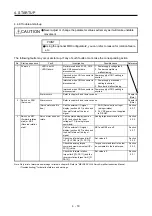
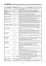
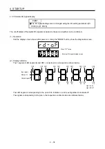
4.5.3 Status display mode
The servo status during operation is shown on the 5-digit, 7-segment LED display. Press the "UP" or
"DOWN" button to change display data as desired. When the required data is selected, the corresponding
symbol is displayed. Press the "SET" button to display that data. At only power-on, however, data appears
after the symbol of the status display selected in [Pr. PC36] has been shown for 2 s.
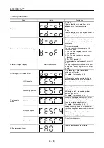
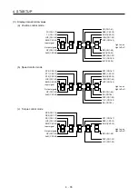
(1) Display transition
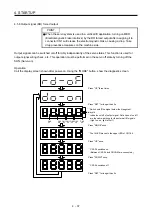
After selecting the status display mode with the "MODE" button, pressing the "UP" or "DOWN" button
changes the display as shown below.
(a) Standard control mode
Regenerative load ratio
Cumulative feedback
pulses
Effective load ratio
Peak load ratio
Instantaneous torque
Within one-revolution
position (1 pulse unit)
Servo motor speed/
Linear servo motor speed
Within one-revolution position
(1000 pulse unit)
Droop pulses
ABS counter
Cumulative command
pulses
Load to motor inertia ratio
Command pulse
frequency
Bus voltage
Encoder inside temperature
Settling time
Oscillation detection frequency
Number of tough drives
Unit power consumption 1
(increment of 1 W)
Unit total power consumption 1
(increment of 1 Wh)
Unit power consumption 2
(increment of 1 kW)
Unit total power consumption 2
(increment of 100 kWh)
Unit total power consumption 2
(increment of 100 kWh)
Cumulative feedback pulses
Analog speed command
voltage
Analog speed limit
voltage
Analog torque limit voltage
Analog torque command
voltage
DOWN
UP
Summary of Contents for MR-J4-100A
Page 9: ...A 8 MEMO ...
Page 61: ...1 FUNCTIONS AND CONFIGURATION 1 44 MEMO ...
Page 67: ...2 INSTALLATION 2 6 MEMO ...
Page 137: ...3 SIGNALS AND WIRING 3 70 MEMO ...
Page 261: ...6 NORMAL GAIN ADJUSTMENT 6 24 MEMO ...
Page 291: ...7 SPECIAL ADJUSTMENT FUNCTIONS 7 30 MEMO ...
Page 299: ...8 TROUBLESHOOTING 8 8 MEMO ...
Page 319: ...9 OUTLINE DRAWINGS 9 20 MEMO ...
Page 461: ...12 ABSOLUTE POSITION DETECTION SYSTEM 12 36 MEMO ...
Page 511: ...14 COMMUNICATION FUNCTION 14 38 MEMO ...
Page 559: ...16 USING A DIRECT DRIVE MOTOR 16 20 MEMO ...
Page 583: ...17 FULLY CLOSED LOOP SYSTEM 17 24 MEMO ...
Page 621: ...APPENDIX App 38 ...
Page 639: ......