


3. SIGNALS AND WIRING
3 - 35
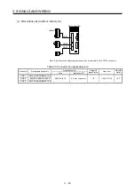
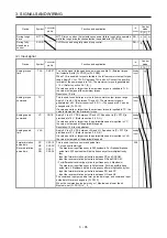
Control
mode
Device Symbol
Connector
pin No.
Function and application
I/O
division
P S
T
During tough
drive
MTTR
MTTR turns on when the instantaneous power failure tough drive operates
while the tough drive function selection is enabled with [Pr. PA20].
DO-1
During fully
closed loop
control
CLDS
CLDS turns on during fully closed loop control.
DO-1
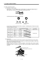
(2) Input signal
Control
mode
Device Symbol
Connector
pin No.
Function and application
I/O
division
P S
T
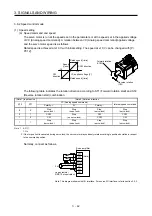
Analog torque
limit
TLA
CN1-27 To use the signal in the speed control mode, enable TL (External torque
limit selection) with [Pr. PD23] to [Pr. PD28].
When TLA is enabled, torque is limited in the full servo motor output torque
range. Apply 0 V to +10 V DC between TLA and LG. Connect the positive
terminal of the power supply to TLA. The maximum torque is generated at
+10 V. (Refer to section 3.6.1 (5).)
If a value equal to or larger than the maximum torque is inputted to TLA,
the value is clamped at the maximum torque.
Resolution: 10 bits
Analog
input
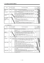
Analog torque
command
TC
This is used to control torque in the full servo motor output torque range.
Apply 0 V to ±8 V DC between TC and LG. The maximum torque is
generated at ±8 V. (Refer to section 3.6.3 (1).) The speed at ±8 V can be
changed with [Pr. PC13].
If a value equal to or larger than the maximum torque is inputted to TC, the
value is clamped at the maximum torque.
Analog
input
Analog speed
command
VC
CN1-2
Apply 0 V to ±10 V DC between VC and LG. Speed set in [Pr. PC12] is
provided at ±10 V. (Refer to section 3.6.2 (1).)
If a value equal to or larger than the permissible speed is inputted to VC,
the value is clamped at the permissible speed.
Resolution: 14 bits or equivalent
Analog
input
Analog speed
limit
VLA
Apply 0 V to ±10 V DC between VLA and LG. Speed set in [Pr. PC12] is
provided at ±10 V. (Refer to section 3.6.3 (3).)
If a value equal to or larger than the permissible speed is inputted to VLA,
the value is clamped at the permissible speed.
Analog
input
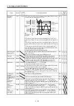
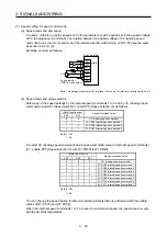
Forward rotation
pulse train
Reverse rotation
pulse train
PP
NP
PG
NG
CN1-10
CN1-35
CN1-11
CN1-36
This is used to enter a command pulse train.
For open-collector type
The maximum input frequency is 200 kpulses/s. For A-phase/B-phase
pulse train, 200 kpulses/s will be the frequency after multiplication by
four.
Input the forward rotation pulse train between PP and DOCOM.
Input the reverse rotation pulse train between NP and DOCOM.
For differential receiver type (max. input frequency: 4 Mpulses/s)
The maximum input frequency is 4 Mpulses/s. For A-phase/B-phase
pulse train, 4 Mpulses/s will be the frequency after multiplication by four.
Input the forward rotation pulse train between PG and PP.
Input the reverse rotation pulse train between NG and NP.
The command input pulse train form, pulse train logic, and command input
pulse train filter are changed in [Pr. PA13].
When the command pulse train is over 1 Mpulse/s and lower than 4
Mpulse/s, set [Pr. PA13] to "_ 0 _ _".
DI-2
Summary of Contents for MR-J4-100A
Page 9: ...A 8 MEMO ...
Page 61: ...1 FUNCTIONS AND CONFIGURATION 1 44 MEMO ...
Page 67: ...2 INSTALLATION 2 6 MEMO ...
Page 137: ...3 SIGNALS AND WIRING 3 70 MEMO ...
Page 261: ...6 NORMAL GAIN ADJUSTMENT 6 24 MEMO ...
Page 291: ...7 SPECIAL ADJUSTMENT FUNCTIONS 7 30 MEMO ...
Page 299: ...8 TROUBLESHOOTING 8 8 MEMO ...
Page 319: ...9 OUTLINE DRAWINGS 9 20 MEMO ...
Page 461: ...12 ABSOLUTE POSITION DETECTION SYSTEM 12 36 MEMO ...
Page 511: ...14 COMMUNICATION FUNCTION 14 38 MEMO ...
Page 559: ...16 USING A DIRECT DRIVE MOTOR 16 20 MEMO ...
Page 583: ...17 FULLY CLOSED LOOP SYSTEM 17 24 MEMO ...
Page 621: ...APPENDIX App 38 ...
Page 639: ......