


11. OPTIONS AND AUXILIARY EQUIPMENT
11 - 30
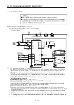
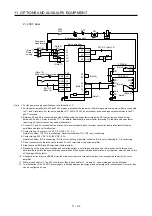
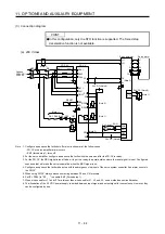
(3) Connection instructions
The cables between the servo amplifier and the brake unit, and between the resistor unit and the brake
unit should be as short as possible. Always twist the cable longer than 5 m (twist five times or more per
one meter). Even when the cable is twisted, the cable should be less than 10 m. Using cables longer
than 5 m without twisting or twisted cables longer than 10 m, may result in the brake unit malfunction.
Servo amplifier
Brake unit
5 m or shorter
5 m or shorter
Servo amplifier
Brake unit
10 m or shorter
10 m or shorter
P+
N-
P/+
N/-
P
PR
P
PR
P/+
N/-
P
PR
P
PR
Twist
Twist
Resistor unit
Resistor unit
P+
N-
Summary of Contents for MR-J4-100A
Page 9: ...A 8 MEMO ...
Page 61: ...1 FUNCTIONS AND CONFIGURATION 1 44 MEMO ...
Page 67: ...2 INSTALLATION 2 6 MEMO ...
Page 137: ...3 SIGNALS AND WIRING 3 70 MEMO ...
Page 261: ...6 NORMAL GAIN ADJUSTMENT 6 24 MEMO ...
Page 291: ...7 SPECIAL ADJUSTMENT FUNCTIONS 7 30 MEMO ...
Page 299: ...8 TROUBLESHOOTING 8 8 MEMO ...
Page 319: ...9 OUTLINE DRAWINGS 9 20 MEMO ...
Page 461: ...12 ABSOLUTE POSITION DETECTION SYSTEM 12 36 MEMO ...
Page 511: ...14 COMMUNICATION FUNCTION 14 38 MEMO ...
Page 559: ...16 USING A DIRECT DRIVE MOTOR 16 20 MEMO ...
Page 583: ...17 FULLY CLOSED LOOP SYSTEM 17 24 MEMO ...
Page 621: ...APPENDIX App 38 ...
Page 639: ......