


3. SIGNALS AND WIRING
3 - 49
(c) SA (Speed reached)
As in section 3.6.2 (2)
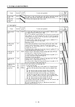
3.6.5 Speed/torque control switching mode
Set " _ _ _ 3" in [Pr. PA01] to switch to the speed/torque control switching mode.
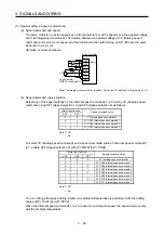
(1) LOP (control switching)
Use LOP (Control switching) to switch between the speed control mode and the torque control mode
with an external contact. The following shows a relation between LOP and control modes.
(Note)
LOP
Control mode
0
Speed control mode
1
Torque control mode
Note. 0: Off
1: On
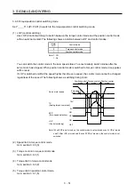
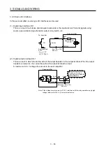
The control mode may be switched at any time. The following shows a switching timing chart.
LOP
(Control switching)
Servo motor speed
TC
(Analog torque command)
ON
OFF
10V
0
(Note)
Load torque
Speed control
mode
Torque control
mode
Speed control
mode
Forward rotation
in driving mode
Note. When ST1 (Forward rotation start) and ST2 (Reverse rotation start) are switched off
as soon as a mode is switched to the speed control, the servo motor comes to a stop
according to the deceleration time constant. A shock may occur at switching control
modes.
(2) Speed setting in speed control mode
As in section 3.6.2 (1)
(3) Torque limit in speed control mode
As in section 3.6.1 (5)
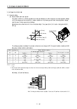
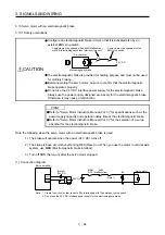
(4) Speed limit in torque control mode
(a) Speed limit value and speed
The speed is limited to the limit value of the parameter or the value set in the applied voltage of VLA
(Analog speed limit).
A relation between the VLA (Analog speed limit) applied voltage and the limit value is as in section
3.6.3 (3) (a).
Summary of Contents for MR-J4-100A
Page 9: ...A 8 MEMO ...
Page 61: ...1 FUNCTIONS AND CONFIGURATION 1 44 MEMO ...
Page 67: ...2 INSTALLATION 2 6 MEMO ...
Page 137: ...3 SIGNALS AND WIRING 3 70 MEMO ...
Page 261: ...6 NORMAL GAIN ADJUSTMENT 6 24 MEMO ...
Page 291: ...7 SPECIAL ADJUSTMENT FUNCTIONS 7 30 MEMO ...
Page 299: ...8 TROUBLESHOOTING 8 8 MEMO ...
Page 319: ...9 OUTLINE DRAWINGS 9 20 MEMO ...
Page 461: ...12 ABSOLUTE POSITION DETECTION SYSTEM 12 36 MEMO ...
Page 511: ...14 COMMUNICATION FUNCTION 14 38 MEMO ...
Page 559: ...16 USING A DIRECT DRIVE MOTOR 16 20 MEMO ...
Page 583: ...17 FULLY CLOSED LOOP SYSTEM 17 24 MEMO ...
Page 621: ...APPENDIX App 38 ...
Page 639: ......