


3. SIGNALS AND WIRING
3 - 62
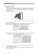
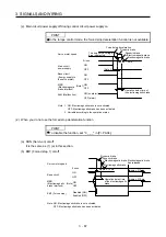
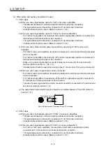
2) Output pulse
/2
T
400 s or more
Time cycle (T) is determined by the settings of
[Pr. PA15] and [Pr. PC19].
LA
LAR
LB
LBR
LZ
LZR
OP
Servo motor CCW rotation
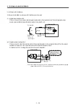
(5) Analog input
Input impedance
10 k
Ω
to 12 k
Ω
VC etc.
LG
P15R
SD
Approx.
10 k
Ω
+15 V DC
Upper limit setting
2 k
Ω
2 k
Ω
Servo amplifier
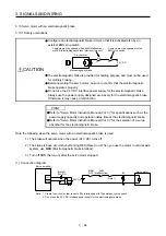
(6) Analog output
Output voltage: ±10 V (Note)
Maximum output current: 1 mA
Resolution: 10 bits or equivalent
LG
MO1
(MO2)
Servo amplifier
Note. Output voltage range varies depending on the monitored signal.
Summary of Contents for MR-J4-100A
Page 9: ...A 8 MEMO ...
Page 61: ...1 FUNCTIONS AND CONFIGURATION 1 44 MEMO ...
Page 67: ...2 INSTALLATION 2 6 MEMO ...
Page 137: ...3 SIGNALS AND WIRING 3 70 MEMO ...
Page 261: ...6 NORMAL GAIN ADJUSTMENT 6 24 MEMO ...
Page 291: ...7 SPECIAL ADJUSTMENT FUNCTIONS 7 30 MEMO ...
Page 299: ...8 TROUBLESHOOTING 8 8 MEMO ...
Page 319: ...9 OUTLINE DRAWINGS 9 20 MEMO ...
Page 461: ...12 ABSOLUTE POSITION DETECTION SYSTEM 12 36 MEMO ...
Page 511: ...14 COMMUNICATION FUNCTION 14 38 MEMO ...
Page 559: ...16 USING A DIRECT DRIVE MOTOR 16 20 MEMO ...
Page 583: ...17 FULLY CLOSED LOOP SYSTEM 17 24 MEMO ...
Page 621: ...APPENDIX App 38 ...
Page 639: ......