


17. FULLY CLOSED LOOP SYSTEM
17 - 9
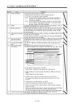
17.2.4 MR-J4FCCBL03M branch cable
Use MR-J4FCCBL03M branch cable to connect the rotary encoder and the load-side encoder to CN2
connector.
When fabricating the branch cable using MR-J3THMCN2 connector set, refer to "Linear Encoder Instruction
Manual".
LG
View seen from wiring side.
4
MRR
2
LG
8
6
1
P5
5
10
3
MR
7
9
THM2
THM1
MXR
SEL
THM2
THM1
SEL
MX
BAT
SD
3
4
1
CN2
MOTOR
Plate
(Note 1)
(Note 2)
0.3 m
MR
P5
MRR
SD
MR
P5
MRR
3
4
1
Plate
View seen from wiring side.
4
MRR
2
8
6
1
P5
5
10
3
MR
7
9
View seen from wiring side.
4
2
8
6
1
5
10
3
7
9
BAT
2
THM2
6
7
MX
LG
LG
2
MXR
8
BAT
SEL
9
10
5
THM1
5
THM1
6
THM2
9
BAT
10
SEL
SCALE
(Note 2)
P5
SD
SEL
LG
1
2
10
Plate
4
MXR
BAT
9
3
MX
BAT
SEL
LG
P5
MXR
MX
Note 1. Receptacle: 36210-0100PL, shell kit: 36310-3200-008 (3M)
2. Plug: 36110-3000FD, shell kit: 36310-F200-008 (3M)
Summary of Contents for MR-J4-100A
Page 9: ...A 8 MEMO ...
Page 61: ...1 FUNCTIONS AND CONFIGURATION 1 44 MEMO ...
Page 67: ...2 INSTALLATION 2 6 MEMO ...
Page 137: ...3 SIGNALS AND WIRING 3 70 MEMO ...
Page 261: ...6 NORMAL GAIN ADJUSTMENT 6 24 MEMO ...
Page 291: ...7 SPECIAL ADJUSTMENT FUNCTIONS 7 30 MEMO ...
Page 299: ...8 TROUBLESHOOTING 8 8 MEMO ...
Page 319: ...9 OUTLINE DRAWINGS 9 20 MEMO ...
Page 461: ...12 ABSOLUTE POSITION DETECTION SYSTEM 12 36 MEMO ...
Page 511: ...14 COMMUNICATION FUNCTION 14 38 MEMO ...
Page 559: ...16 USING A DIRECT DRIVE MOTOR 16 20 MEMO ...
Page 583: ...17 FULLY CLOSED LOOP SYSTEM 17 24 MEMO ...
Page 621: ...APPENDIX App 38 ...
Page 639: ......