


5. PARAMETERS
5 - 45
Control
mode
No./symbol/
name
Setting
digit
Function
Initial
value
[unit]
P S T
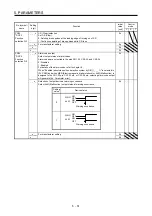
PC54
RSUP1
Vertical axis
freefall
prevention
compensation
amount
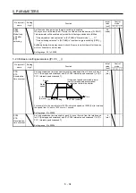
Set the compensation amount of the vertical axis freefall prevention function.
Set it per servo motor rotation amount or linear servo motor travel distance.
When setting a positive value, the servo motor or linear servo motor moves in the
direction set with [Pr. PA14] for the forward rotation pulse input. When setting a
negative value, the servo motor or linear servo motor moves in the direction set with
[Pr. PA14] for the reverse rotation pulse input.
For example, if a positive compensation amount is set when the [Pr. PA14 Rotation
direction selection/travel direction selection] setting is "1", compensation will be
performed to the CW direction.
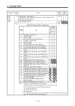
The vertical axis freefall prevention function is performed when all of the following
conditions are met.
1) Position control mode
2) The value of the parameter is other than "0".
3) The forced stop deceleration function is enabled.
4) Alarm occurs or EM2 turns off when the (linear) servo motor speed is zero speed
or less.
5) MBR (Electromagnetic brake interlock) is enabled with [Pr. PD23] to [Pr. PD28],
and the base circuit shut-off delay time is set in [Pr. PC16].
Setting range: -25000 to 25000
0
[0.0001
rev]/
[0.01
mm]
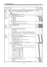
_ _ _ x Motor-less operation selection
This is used to select the motor-less operation. This is not used in the linear servo
motor control mode, fully closed loop control, and DD motor control mode.
0: Disabled
1: Enabled
0h
_ _ x _ For manufacturer setting
0h
_ x _ _
0h
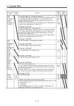
PC60
*COPD
Function
selection C-D
x _ _ _
0h
Summary of Contents for MR-J4-100A
Page 9: ...A 8 MEMO ...
Page 61: ...1 FUNCTIONS AND CONFIGURATION 1 44 MEMO ...
Page 67: ...2 INSTALLATION 2 6 MEMO ...
Page 137: ...3 SIGNALS AND WIRING 3 70 MEMO ...
Page 261: ...6 NORMAL GAIN ADJUSTMENT 6 24 MEMO ...
Page 291: ...7 SPECIAL ADJUSTMENT FUNCTIONS 7 30 MEMO ...
Page 299: ...8 TROUBLESHOOTING 8 8 MEMO ...
Page 319: ...9 OUTLINE DRAWINGS 9 20 MEMO ...
Page 461: ...12 ABSOLUTE POSITION DETECTION SYSTEM 12 36 MEMO ...
Page 511: ...14 COMMUNICATION FUNCTION 14 38 MEMO ...
Page 559: ...16 USING A DIRECT DRIVE MOTOR 16 20 MEMO ...
Page 583: ...17 FULLY CLOSED LOOP SYSTEM 17 24 MEMO ...
Page 621: ...APPENDIX App 38 ...
Page 639: ......