


1. FUNCTIONS AND CONFIGURATION
1 - 29
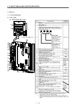
1.7.2 Removal and reinstallation of the front cover
CAUTION
Before removing or installing the front cover, turn off the power and wait for 15
minutes or more until the charge lamp turns off. Then, confirm that the voltage
between P+ and N- is safe with a voltage tester and others. Otherwise, an electric
shock may occur. In addition, when confirming whether the charge lamp is off or
not, always confirm it from the front of the servo amplifier.
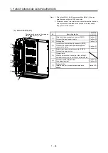
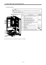
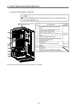
The following shows how to remove and reinstall the front cover of MR-J4-700A(-RJ) to MR-J4-22KA(-RJ)
and MR-J4-500A4(-RJ) to MR-J4-22KA4(-RJ).
The diagram shows MR-J4-700A.
Removal of the front cover
A)
A)
1) Hold the ends of lower side of the front cover with
both hands.
2) Pull up the cover, supporting at point A).
3) Pull out the front cover to remove. Hold the ends of
lower side of the front cover with both hands.
Summary of Contents for MR-J4-100A
Page 9: ...A 8 MEMO ...
Page 61: ...1 FUNCTIONS AND CONFIGURATION 1 44 MEMO ...
Page 67: ...2 INSTALLATION 2 6 MEMO ...
Page 137: ...3 SIGNALS AND WIRING 3 70 MEMO ...
Page 261: ...6 NORMAL GAIN ADJUSTMENT 6 24 MEMO ...
Page 291: ...7 SPECIAL ADJUSTMENT FUNCTIONS 7 30 MEMO ...
Page 299: ...8 TROUBLESHOOTING 8 8 MEMO ...
Page 319: ...9 OUTLINE DRAWINGS 9 20 MEMO ...
Page 461: ...12 ABSOLUTE POSITION DETECTION SYSTEM 12 36 MEMO ...
Page 511: ...14 COMMUNICATION FUNCTION 14 38 MEMO ...
Page 559: ...16 USING A DIRECT DRIVE MOTOR 16 20 MEMO ...
Page 583: ...17 FULLY CLOSED LOOP SYSTEM 17 24 MEMO ...
Page 621: ...APPENDIX App 38 ...
Page 639: ......