


17. FULLY CLOSED LOOP SYSTEM
17 - 22
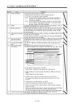
17.3.8 About MR Configurator2
Using MR Configurator2 can confirm if the parameter setting is normal or if the servo motor and the load-
side encoder operate properly.
This section explains the fully closed diagnosis screen.
Click "Monitor start" to constantly read the monitor display items from the servo amplifier.
Then, click "Monitor stop" to stop reading.Click "Parameter read" to read the parameter items from the servo
amplifier, and then click "Parameter write" to write them.
f)
a)
c)
k)
b)
i)
h)
g)
d) e)
j)
l)
m)
n)
Symbol Name
Explanation
Unit
a)
Motor-side cumu. feedback
pulses
(after gear)
Feedback pulses from the servo motor encoder are counted and displayed. (load-side
encoder unit)
When the set value exceeds 999999999, it starts with 0.
Click "Clear" to reset the value to 0.
The "-" symbol is indicated for reverse.
pulse
b)
Motor-side droop pulses
Droop pulses of the deviation counter between a servo motor-side position and a
command are displayed.
The "-" symbol is indicated for reverse.
pulse
c) Cumulative
command
pulses
Position command input pulses are counted and displayed.
Click "Clear" to reset the value to 0.
The "-" symbol is indicated for reverse command.
pulse
d) Load-side
cumulative
feedback pulses
Feedback pulses from the load-side encoder are counted and displayed.
When the set value exceeds 999999999, it starts with 0.
Click "Clear" to reset the value to 0.
The "-" symbol is indicated for reverse.
pulse
e)
Load-side droop pulses
Droop pulses of the deviation counter between a load-side position and a command are
displayed.
The "-" symbol is indicated for reverse.
pulse
f)
Motor-side cumu. feedback
pulses
(Before Gear)
Feedback pulses from the servo motor encoder are counted and displayed. (Servo
motor encoder unit)
When the set value exceeds 999999999, it starts with 0.
Click "Clear" to reset the value to 0.
The "-" symbol is indicated for reverse.
pulse
Summary of Contents for MR-J4-100A
Page 9: ...A 8 MEMO ...
Page 61: ...1 FUNCTIONS AND CONFIGURATION 1 44 MEMO ...
Page 67: ...2 INSTALLATION 2 6 MEMO ...
Page 137: ...3 SIGNALS AND WIRING 3 70 MEMO ...
Page 261: ...6 NORMAL GAIN ADJUSTMENT 6 24 MEMO ...
Page 291: ...7 SPECIAL ADJUSTMENT FUNCTIONS 7 30 MEMO ...
Page 299: ...8 TROUBLESHOOTING 8 8 MEMO ...
Page 319: ...9 OUTLINE DRAWINGS 9 20 MEMO ...
Page 461: ...12 ABSOLUTE POSITION DETECTION SYSTEM 12 36 MEMO ...
Page 511: ...14 COMMUNICATION FUNCTION 14 38 MEMO ...
Page 559: ...16 USING A DIRECT DRIVE MOTOR 16 20 MEMO ...
Page 583: ...17 FULLY CLOSED LOOP SYSTEM 17 24 MEMO ...
Page 621: ...APPENDIX App 38 ...
Page 639: ......