


12. ABSOLUTE POSITION DETECTION SYSTEM
12 - 18
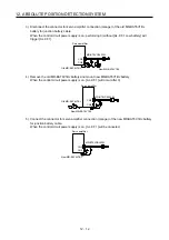
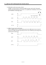
1) After the absolute position data is transmitted, RD turns on by ABSM-off. When RD is on, ABSM-
on is not received.
2) Even if SON is turned on before ABSM is turned on, the base circuit is not turned on until ABSM
is turned on.
If a servo alarm has occurred, ABSM is not received. ABSM allows data transmission even while
a servo warning is occurring.
3) If ABSM is turned off during the ABS transfer mode, the ABS transfer mode is interrupted and
[AL. E5 ABS time-out warning] occurs.
If SON is turned off, RES is turned on, and EM2 is turned off during the ABS transfer mode, [AL.
E5 ABS time-out warning] occurs.
4) Note that if ABSM is turned on for a purpose other than absolute position data transmission, the
output signals will be assigned the functions of absolute position data transmission.
Output signal
CN1 Pin No.
ABSM (ABS transfer mode): off ABSM (ABS transfer mode): on
22
Positioning completion
transmission data bit 03
23
Zero speed detection
transmission data bit 1
25
During torque limit control
transmission data ready
5) ABSM is not accepted while the base circuit is on. For re-transferring, turn off SON signal and
keep the base circuit in the off state for 20 ms or longer.
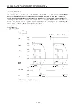
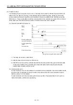
(b) Detailed description of absolute position data transfer
OFF
ON
OFF
ON
OFF
ON
OFF
ON
OFF
ON
3)
4)
5)
7)
(Note)
1)
2)
6)
Servo-on in
programmable
controller
SON
ABSM
ABSR
ABST
ABSB0
ABSB1
During transfer of ABS
Lower
2 bits
Checksum
Upper 2 bits
Note. If SON does not turn on within 1 s after ABSM off, [AL. EA ABS servo-on warning] will occur. But it will not
influence the transfer. SON on will cancel [AL. EA] automatically.
Summary of Contents for MR-J4-100A
Page 9: ...A 8 MEMO ...
Page 61: ...1 FUNCTIONS AND CONFIGURATION 1 44 MEMO ...
Page 67: ...2 INSTALLATION 2 6 MEMO ...
Page 137: ...3 SIGNALS AND WIRING 3 70 MEMO ...
Page 261: ...6 NORMAL GAIN ADJUSTMENT 6 24 MEMO ...
Page 291: ...7 SPECIAL ADJUSTMENT FUNCTIONS 7 30 MEMO ...
Page 299: ...8 TROUBLESHOOTING 8 8 MEMO ...
Page 319: ...9 OUTLINE DRAWINGS 9 20 MEMO ...
Page 461: ...12 ABSOLUTE POSITION DETECTION SYSTEM 12 36 MEMO ...
Page 511: ...14 COMMUNICATION FUNCTION 14 38 MEMO ...
Page 559: ...16 USING A DIRECT DRIVE MOTOR 16 20 MEMO ...
Page 583: ...17 FULLY CLOSED LOOP SYSTEM 17 24 MEMO ...
Page 621: ...APPENDIX App 38 ...
Page 639: ......