


14. COMMUNICATION FUNCTION
14 - 18
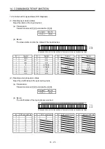
14.5 Detailed explanations of commands
14.5.1 Data processing
When the master station transmits a command data No. or a c data No. + data to a slave station,
the servo amplifier returns a response or data in accordance with the purpose.
When numerical values are represented in these send data and receive data, they are represented in
decimal, hexadecimal, etc.
Therefore, data must be processed in accordance with the application.
Since whether data must be processed or not and how to process data depend on the monitoring,
parameters, etc., follow the detailed explanation of the corresponding command.
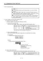
The following methods are how to process send and receive data when reading and writing data.
(1) Processing a read data
When the display type is 0, the eight-character data is converted from hexadecimal to decimal and a
decimal point is placed according to the decimal point position information.
When the display type is 1, the eight-character data is used unchanged.
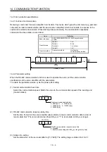
The following example indicates how to process the receive data "003000000929" given to show.
The receive data is as follows.
0 0 3 0 0 0 0 0 0 9 2 9
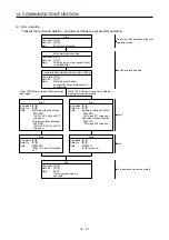
Display type
0: Data must be converted into decimal.
1: Data is used unchanged in hexadecimal.
Decimal point position
0: No decimal point
1: First least significant digit (normally not used)
2: Second least significant digit
3: Third least significant digit
4: Forth least significant digit
5: Fifth least significant digit
6: Sixth least significant digit
Data 32-bit length (hexadecimal representation)
(Data conversion is required as indicated in the display type.)
Since the display type is "0" in this case, the hexadecimal data is converted into decimal.
00000929H
→
2345
As the decimal point position is "3", a decimal point is placed in the third least significant digit.
Hence, "23.45" is displayed.
Summary of Contents for MR-J4-100A
Page 9: ...A 8 MEMO ...
Page 61: ...1 FUNCTIONS AND CONFIGURATION 1 44 MEMO ...
Page 67: ...2 INSTALLATION 2 6 MEMO ...
Page 137: ...3 SIGNALS AND WIRING 3 70 MEMO ...
Page 261: ...6 NORMAL GAIN ADJUSTMENT 6 24 MEMO ...
Page 291: ...7 SPECIAL ADJUSTMENT FUNCTIONS 7 30 MEMO ...
Page 299: ...8 TROUBLESHOOTING 8 8 MEMO ...
Page 319: ...9 OUTLINE DRAWINGS 9 20 MEMO ...
Page 461: ...12 ABSOLUTE POSITION DETECTION SYSTEM 12 36 MEMO ...
Page 511: ...14 COMMUNICATION FUNCTION 14 38 MEMO ...
Page 559: ...16 USING A DIRECT DRIVE MOTOR 16 20 MEMO ...
Page 583: ...17 FULLY CLOSED LOOP SYSTEM 17 24 MEMO ...
Page 621: ...APPENDIX App 38 ...
Page 639: ......