


15. USING A LINEAR SERVO MOTOR
15 - 12
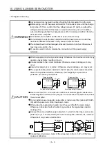
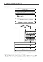
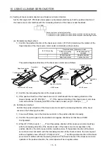
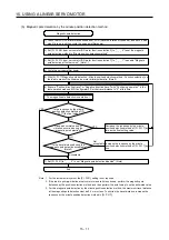
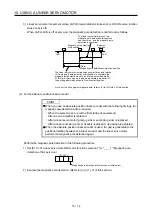
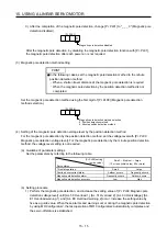
(2) Operation at the magnetic pole detection
WARNING
Note that the magnetic pole detection automatically starts simultaneously with the
turning-on of the servo-on command.
CAUTION
If the magnetic pole detection is not executed properly, the linear servo motor
may operate unexpectedly.
POINT
Establish the machine configuration to use LSP (Upper stroke end) and LSN
(Lower stroke end). The machine may be damaged due to a collision without
LSP and LSN.
Assign LSP and LSN and perform the magnetic pole detection also in the torque
control mode.
At the magnetic pole detection, whether the linear servo motor moves in the
positive or negative direction is unpredictable.
Depending on the setting value of [Pr. PL09 Magnetic pole detection voltage
level], an overload, overcurrent, magnetic pole detection alarm, or others may
occur.
After the magnetic pole detection, check the positioning accuracy with the test
operation (positioning operation function) of MR Configurator2.
When the absolute position linear encoder is used, if a gap is generated to the
positional relation between the linear encoder and the linear servo motor,
perform the magnetic pole detection again.
The accuracy of the magnetic pole detection improves with no load.
A servo alarm may occur when the linear encoder is not mounted properly, or
when the linear encoder resolution setting ([Pr. PL02] and [Pr. PL03]) or the
setting value of [Pr. PL09 Magnetic pole detection voltage level] is incorrect.
For the machine that its friction becomes 30% or more of the continuous thrust,
the linear servo motor may not operate properly after the magnetic pole
detection.
For the horizontal shaft of the machine that its unbalanced thrust becomes 20%
or more of the continuous thrust, the linear servo motor may not operate
properly after the magnetic pole detection.
For the machine that multiple axes are connected like a tandem configuration, if
you try to perform the magnetic pole detection simultaneously for multiple axes,
the magnetic pole detection may not be executed. Perform the magnetic pole
detection for each axis. At this time, set the axes that the magnetic pole
detection is not performed for to servo-off.
Summary of Contents for MR-J4-100A
Page 9: ...A 8 MEMO ...
Page 61: ...1 FUNCTIONS AND CONFIGURATION 1 44 MEMO ...
Page 67: ...2 INSTALLATION 2 6 MEMO ...
Page 137: ...3 SIGNALS AND WIRING 3 70 MEMO ...
Page 261: ...6 NORMAL GAIN ADJUSTMENT 6 24 MEMO ...
Page 291: ...7 SPECIAL ADJUSTMENT FUNCTIONS 7 30 MEMO ...
Page 299: ...8 TROUBLESHOOTING 8 8 MEMO ...
Page 319: ...9 OUTLINE DRAWINGS 9 20 MEMO ...
Page 461: ...12 ABSOLUTE POSITION DETECTION SYSTEM 12 36 MEMO ...
Page 511: ...14 COMMUNICATION FUNCTION 14 38 MEMO ...
Page 559: ...16 USING A DIRECT DRIVE MOTOR 16 20 MEMO ...
Page 583: ...17 FULLY CLOSED LOOP SYSTEM 17 24 MEMO ...
Page 621: ...APPENDIX App 38 ...
Page 639: ......