
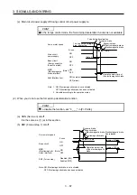


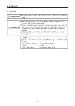

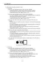


4. STARTUP
4 - 10
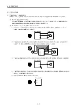
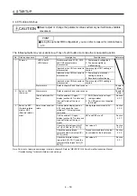
No. Start-up
sequence
Fault
Investigation Possible
cause
Reference
2
Switch on SON
(Servo-on).
Alarm occurs.
Refer to chapter 8 and remove cause.
Chapter 8
(Note)
Servo motor shaft is
not servo-locked.
(Servo motor shaft is
free.)
1. Check the display to see if the
servo amplifier is ready to
operate.
2. Check the external I/O signal
indication (section 4.5.7) to see
if SON (Servo-on) is on.
1. SON (Servo-on) is not input.
(wiring mistake)
2. 24 V DC power is not
supplied to DICOM.
Section
4.5.7
3 Input
command
pulse.
(Test operation)
Servo motor does not
rotate.
Check the cumulative command
pulse on the status display
(section 4.5.3).
1. Wiring mistake
(a) For open collector pulse
train input, 24 V DC power
is not supplied to OPC.
(b) LSP and LSN are not on.
2. Pulse is not input from the
controller.
Section
4.5.3
Mistake in setting of [Pr. PA13].
Servo motor run in
reverse direction.
1. Mistake in wiring to controller.
2. Mistake in setting of [Pr.
PA14].
Chapter 5
4 Gain
adjustment Rotation ripples (speed
fluctuations) are large
at low speed.
Make gain adjustment in the
following procedure.
1. Increase the auto tuning
response level.
2. Repeat acceleration and
deceleration several times to
complete auto tuning.
Gain adjustment fault
Chapter 6
Large load inertia
moment causes the
servo motor shaft to
oscillate side to side.
If the servo motor may be run with
safety, repeat acceleration and
deceleration several times to
complete auto tuning.
Gain adjustment fault
Chapter 6
5
Cyclic operation
Position shift occurs
Confirm the cumulative command
pulses, cumulative feedback
pulses and actual servo motor
position.
Pulse counting error, etc. due to
noise.
(2) in this
section
Note. Only a list of alarms and warnings is listed in chapter 8. Refer to "MELSERVO-J4 Servo Amplifier Instruction Manual
(Troubleshooting)" for details of alarms and warnings.
Summary of Contents for MR-J4-100A
Page 9: ...A 8 MEMO ...
Page 61: ...1 FUNCTIONS AND CONFIGURATION 1 44 MEMO ...
Page 67: ...2 INSTALLATION 2 6 MEMO ...
Page 137: ...3 SIGNALS AND WIRING 3 70 MEMO ...
Page 261: ...6 NORMAL GAIN ADJUSTMENT 6 24 MEMO ...
Page 291: ...7 SPECIAL ADJUSTMENT FUNCTIONS 7 30 MEMO ...
Page 299: ...8 TROUBLESHOOTING 8 8 MEMO ...
Page 319: ...9 OUTLINE DRAWINGS 9 20 MEMO ...
Page 461: ...12 ABSOLUTE POSITION DETECTION SYSTEM 12 36 MEMO ...
Page 511: ...14 COMMUNICATION FUNCTION 14 38 MEMO ...
Page 559: ...16 USING A DIRECT DRIVE MOTOR 16 20 MEMO ...
Page 583: ...17 FULLY CLOSED LOOP SYSTEM 17 24 MEMO ...
Page 621: ...APPENDIX App 38 ...
Page 639: ......