


1. FUNCTIONS AND CONFIGURATION
1 - 31
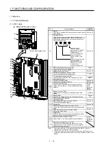
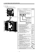
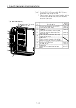
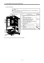
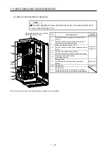
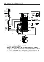
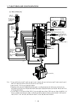
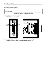
1.8 Configuration including peripheral equipment
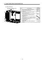
CAUTION
Connecting a servo motor of the wrong axis to U, V, W, or CN2 of the servo
amplifier may cause a malfunction.
POINT
Equipment other than the servo amplifier and servo motor are optional or
recommended products.
(1) 200 V class
(a) MR-J4-200A(-RJ) or less
The diagram shows MR-J4-20A-RJ.
CN4
CN5
P+
C
L11
L21
P3
P4
MR Configurator2
CN3
CN6
CN8
CN1
CN2
W
V
U
L1
L2
L3
R S T
CN2L (
Note
4)
Line noise
filter
(FR-BSF01)
Regenerative
option
Servo motor
Personal
computer
(Note 3)
Magnetic
contactor
(MC)
Power factor
improving DC
reactor
(FR-HEL)
Molded-case
circuit breaker
(MCCB)
To safety relay or
MR-J3-D05 safety
logic unit
Junction terminal block
(Note 2)
Power
supply
Battery
Personal computer and other
(Note 1)
Analog monitor
Summary of Contents for MR-J4-100A
Page 9: ...A 8 MEMO ...
Page 61: ...1 FUNCTIONS AND CONFIGURATION 1 44 MEMO ...
Page 67: ...2 INSTALLATION 2 6 MEMO ...
Page 137: ...3 SIGNALS AND WIRING 3 70 MEMO ...
Page 261: ...6 NORMAL GAIN ADJUSTMENT 6 24 MEMO ...
Page 291: ...7 SPECIAL ADJUSTMENT FUNCTIONS 7 30 MEMO ...
Page 299: ...8 TROUBLESHOOTING 8 8 MEMO ...
Page 319: ...9 OUTLINE DRAWINGS 9 20 MEMO ...
Page 461: ...12 ABSOLUTE POSITION DETECTION SYSTEM 12 36 MEMO ...
Page 511: ...14 COMMUNICATION FUNCTION 14 38 MEMO ...
Page 559: ...16 USING A DIRECT DRIVE MOTOR 16 20 MEMO ...
Page 583: ...17 FULLY CLOSED LOOP SYSTEM 17 24 MEMO ...
Page 621: ...APPENDIX App 38 ...
Page 639: ......