
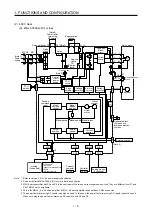


1. FUNCTIONS AND CONFIGURATION
1 - 19
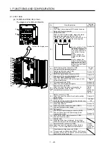
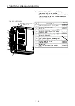
(c) MR-J4-500A(-RJ)
POINT
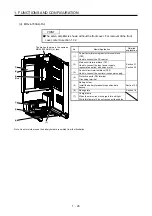
The servo amplifier is shown with the front cover open. The front cover cannot
be removed.
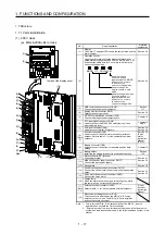
No. Name/Application
Detailed
explanation
(1)
Control circuit terminal block (TE2)
Used to connect the control circuit power supply.
(2)
Main circuit terminal block (TE1)
Connect the input power supply.
Section 3.1
Section 3.3
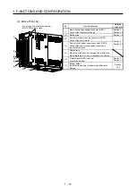
(3)
Battery holder
Install the the battery for absolute position data
backup.
Section
12.2
(4) Rating
plate
Section 1.6
(5)
Regenerative option/power factor improving reactor
terminal block (TE3)
Used to connect a regenerative option or a power
factor improving DC reactor.
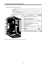
(6)
Servo motor power supply terminal block (TE4)
Connect the servo motor.
Section 3.1
Section 3.3
(7)
Charge lamp
When the main circuit is charged, this will light up.
While this lamp is lit, do not reconnect the cables.
(8)
Protective earth (PE) terminal
Grounding terminal
Section 3.1
Section 3.3
(1)
(3)
(2)
(Note)
(8)
(4)
Side
(5)
(6)
(7)
The broken line area is the same as
MR-J4-200A(-RJ) or less.
Note. Lines for slots around the battery holder are omitted from the illustration.
Summary of Contents for MR-J4-100A
Page 9: ...A 8 MEMO ...
Page 61: ...1 FUNCTIONS AND CONFIGURATION 1 44 MEMO ...
Page 67: ...2 INSTALLATION 2 6 MEMO ...
Page 137: ...3 SIGNALS AND WIRING 3 70 MEMO ...
Page 261: ...6 NORMAL GAIN ADJUSTMENT 6 24 MEMO ...
Page 291: ...7 SPECIAL ADJUSTMENT FUNCTIONS 7 30 MEMO ...
Page 299: ...8 TROUBLESHOOTING 8 8 MEMO ...
Page 319: ...9 OUTLINE DRAWINGS 9 20 MEMO ...
Page 461: ...12 ABSOLUTE POSITION DETECTION SYSTEM 12 36 MEMO ...
Page 511: ...14 COMMUNICATION FUNCTION 14 38 MEMO ...
Page 559: ...16 USING A DIRECT DRIVE MOTOR 16 20 MEMO ...
Page 583: ...17 FULLY CLOSED LOOP SYSTEM 17 24 MEMO ...
Page 621: ...APPENDIX App 38 ...
Page 639: ......