


APPENDIX
App. - 22
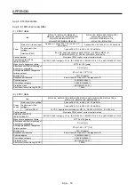
App. 5.7.2 Specifications
Safety logic unit model
MR-J3-D05
Voltage
24 V DC
Control circuit
power supply
Permissible
voltage fluctuation
24 V DC ± 10%
Power supply
capacity
[A]
0.5 (Note 1, 2)
Compatible system
2 systems (A-axis, B-axis independent)
Shut-off input
4 points (2 point × 2 systems)
SDI_: (source/sink compatible) (Note 3)
Shut-off release input
2 points (1 point × 2 systems) SRES_: (source/sink compatible) (Note 3)
Feedback input
2 points (1 point × 2 systems)
TOF_: (source compatible) (Note 3)
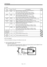
Input type
Photocoupler insulation, 24 V DC (external supply), internal limited resistance 5.4 k
Ω
STO_: (source compatible) (Note 3)
Shut-off output
8 points (4 point × 2 systems)
SDO_: (source/sink compatible) (Note 3)
Output type
Photocoupler insulation, open-collector type
Permissible current: 40 mA/1 output, Inrush current: 100 mA/1 output
Delay time
setting
A-axis: Select from 0 s, 1.4 s, 2.8 s, 5.6 s, 9.8 s, or 30.8 s.
B-axis: Select from 0 s, 1.4 s, 2.8 s, 9.8 s, or 30.8 s.
Accuracy: ±2%
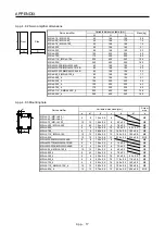
Functional safety
STO, SS1 (IEC/EN 61800-5-2)
EMG STOP, EMG OFF IEC/EN 60204-1)
Standards certified
by CB
EN ISO 13849-1 category 3 PL d, IEC 61508 SIL 2, EN 62061 SIL CL 2, and EN 61800-5-2 SIL 2
Response
performance
(when delay time
is set to 0s)
(Note 4)
10 ms or less (STO input off
→
shut-off output off)
Mean time to
dangerous failure
(MTTFd)
516 years
Diagnosis
converge (DC avg)
93.1%
Average
probability of
dangerous failures
per hour (PFH)
4.75 × 10
-9
[1/h]
Safety
performance
CE marking
LVD: EN 61800-5-1
EMC: EN 61800-3
MD: EN ISO 13849-1, EN 61800-5-2, EN 62061
Compliance to
standards
Natural-cooling, open (IP rating: IP 00)
Structure
Ambient
temperature
0 °C to 55 °C (non-freezing), storage: -20 °C to 65 °C (non-freezing)
Ambient humidity
90 %RH or less (non-condensing), storage: 90 %RH or less (non-condensing)
Ambience
Indoors (no direct sunlight), free from corrosive gas, flammable gas, oil mist, dust, and dirt
Environment
Altitude
Max. 1000 m above sea level
Vibration
resistance
5.9 m/s
2
at 10 Hz to 55 Hz (directions of X, Y, and Z axes)
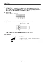
Mass [kg] 0.2
(including CN9 and CN10 connectors)
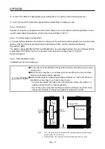
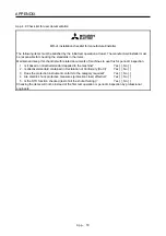
Note 1. Inrush current of approximately 1.5 A flows instantaneously when turning the control circuit power supply on. Select an
appropriate capacity of power supply considering the inrush current.
2. Power-on duration of the safety logic unit is 100,000 times.
3. _: in signal name indicates a number or axis name.
4. For the test pulse input, contact your local sales office.
Summary of Contents for MR-J4-100A
Page 9: ...A 8 MEMO ...
Page 61: ...1 FUNCTIONS AND CONFIGURATION 1 44 MEMO ...
Page 67: ...2 INSTALLATION 2 6 MEMO ...
Page 137: ...3 SIGNALS AND WIRING 3 70 MEMO ...
Page 261: ...6 NORMAL GAIN ADJUSTMENT 6 24 MEMO ...
Page 291: ...7 SPECIAL ADJUSTMENT FUNCTIONS 7 30 MEMO ...
Page 299: ...8 TROUBLESHOOTING 8 8 MEMO ...
Page 319: ...9 OUTLINE DRAWINGS 9 20 MEMO ...
Page 461: ...12 ABSOLUTE POSITION DETECTION SYSTEM 12 36 MEMO ...
Page 511: ...14 COMMUNICATION FUNCTION 14 38 MEMO ...
Page 559: ...16 USING A DIRECT DRIVE MOTOR 16 20 MEMO ...
Page 583: ...17 FULLY CLOSED LOOP SYSTEM 17 24 MEMO ...
Page 621: ...APPENDIX App 38 ...
Page 639: ......