


APPENDIX
App. - 9
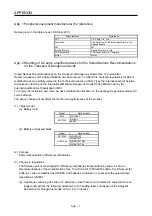
(6) Protect the cables with appropriate ways (routing them in a cabinet, using a cable guard, etc.).
(7) Keep the required clearance/creepage distance depending on voltage you use.
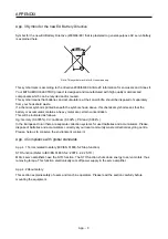
App. 4.2.6 Disposal
Disposal of unusable or irreparable devices should always occur in accordance with the applicable country-
specific waste disposal regulations. (Example: European Waste 16 02 14)
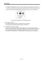
App. 4.2.7 Lithium battery transportation
To transport lithium batteries, take actions to comply with the instructions and regulations such as the United
Nations (UN), the International Civil Aviation Organization (ICAO), and the International Maritime
Organization (IMO).
The battery options (MR-BAT6V1SET and MR-BAT6V1) are assembled batteries from two batteries (lithium
metal battery CR17335A) which are not subject to the dangerous goods (Class 9) of the UN
Recommendations.
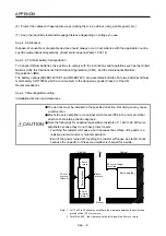
App. 4.3 Mounting/dismounting
Installation direction and clearances
CAUTION
The devices must be installed in the specified direction. Not doing so may cause
a malfunction.
Mount the servo amplifier on a cabinet which meets IP54 in the correct vertical
direction to maintain pollution degree 2.
Note the followings for supplied regenerative resistors of 11 kW to 22 kW servo
amplifiers because they do not have protect covers.
Touching the resistor will cause a burn because the surface of the parts is a
resistive element and very high temperature.
Even if the power turned off, touching the resistor will cause an electric shock
because the capacitor of the servo amplifier is charged for a while.
10 mm
or more
80 mm or longer
for wiring
10 mm
or more
(Note 2)
Top
Bottom
40 mm
or more
(Note 1)
40 mm
or more
Cabinet
Servo amplifier
Servo amplifier
Cabinet
Note 1. For 11 kW to 22 kW servo amplifiers, the clearance between the bottom and
ground will be 120 mm or more.
2. For MR-J4-500_, the clearance on the left side will be 25 mm or more.
Summary of Contents for MR-J4-100A
Page 9: ...A 8 MEMO ...
Page 61: ...1 FUNCTIONS AND CONFIGURATION 1 44 MEMO ...
Page 67: ...2 INSTALLATION 2 6 MEMO ...
Page 137: ...3 SIGNALS AND WIRING 3 70 MEMO ...
Page 261: ...6 NORMAL GAIN ADJUSTMENT 6 24 MEMO ...
Page 291: ...7 SPECIAL ADJUSTMENT FUNCTIONS 7 30 MEMO ...
Page 299: ...8 TROUBLESHOOTING 8 8 MEMO ...
Page 319: ...9 OUTLINE DRAWINGS 9 20 MEMO ...
Page 461: ...12 ABSOLUTE POSITION DETECTION SYSTEM 12 36 MEMO ...
Page 511: ...14 COMMUNICATION FUNCTION 14 38 MEMO ...
Page 559: ...16 USING A DIRECT DRIVE MOTOR 16 20 MEMO ...
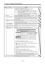
Page 583: ...17 FULLY CLOSED LOOP SYSTEM 17 24 MEMO ...
Page 621: ...APPENDIX App 38 ...
Page 639: ......