


11. OPTIONS AND AUXILIARY EQUIPMENT
11 - 31
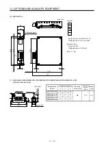
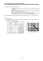
(4) Cables
(a) Cables for the brake unit
For the brake unit, HIV cable (600 V grade heat-resistant PVC insulated wire) is recommended.
1) Main circuit terminal
Crimp
terminal
Wire size
N/-, P/+, PR,
Brake unit
Main
circuit
terminal
screw
size
N/-, P/+,
PR,
Tightening
torque
[N•m]
HIV wire
[mm
2
]
AWG
FR-BU2-15K M4
5.5-4
1.5
3.5
12
FR-BU2-30K M5
5.5-5
2.5
5.5
10
N/-
P/+
PR
Terminal block
200 V
class
FR-BU2-55K M6
14-6
4.4
14
6
FR-BU2-H30K
M4
5.5-4
1.5
3.5
12
FR-BU2-H55K
M5
5.5-5
2.5
5.5
10
400 V
class
FR-BU2-H75K
M6 14-6 4.4 14
6
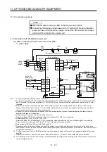
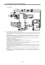
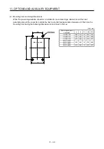
2) Control circuit terminal
POINT
Under tightening can cause a cable disconnection or malfunction. Over
tightening can cause a short circuit or malfunction due to damage to the screw
or the brake unit.
A
RES
PC
B
SD
BUE
C
MSG
SD
MSG
SD SD
Jumper
Terminal block
Insulator
Core
6 mm
Wire the stripped cable after twisting to prevent the cable
from becoming loose. In addition, do not solder it.
Screw size: M3
Tightening torque: 0.5 N•m to 0.6 N•m
Wire size: 0.3 mm
2
to 0.75 mm
2
Screw driver: Small flat-blade screw driver
(Tip thickness: 0.4 mm/Tip width 2.5 mm)
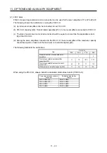
(b) Cables for connecting the servo amplifier and a distribution terminal block when connecting two sets
of the brake unit
Wire size
Brake unit
HIV wire [mm
2
]
AWG
FR-BU2-15K 8 8
Summary of Contents for MR-J4-100A
Page 9: ...A 8 MEMO ...
Page 61: ...1 FUNCTIONS AND CONFIGURATION 1 44 MEMO ...
Page 67: ...2 INSTALLATION 2 6 MEMO ...
Page 137: ...3 SIGNALS AND WIRING 3 70 MEMO ...
Page 261: ...6 NORMAL GAIN ADJUSTMENT 6 24 MEMO ...
Page 291: ...7 SPECIAL ADJUSTMENT FUNCTIONS 7 30 MEMO ...
Page 299: ...8 TROUBLESHOOTING 8 8 MEMO ...
Page 319: ...9 OUTLINE DRAWINGS 9 20 MEMO ...
Page 461: ...12 ABSOLUTE POSITION DETECTION SYSTEM 12 36 MEMO ...
Page 511: ...14 COMMUNICATION FUNCTION 14 38 MEMO ...
Page 559: ...16 USING A DIRECT DRIVE MOTOR 16 20 MEMO ...
Page 583: ...17 FULLY CLOSED LOOP SYSTEM 17 24 MEMO ...
Page 621: ...APPENDIX App 38 ...
Page 639: ......