


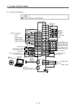


3. SIGNALS AND WIRING
3 - 18
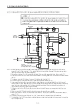
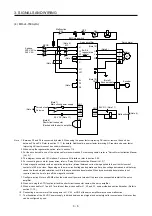
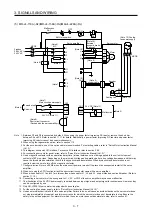
Note 1. To prevent an electric shock, always connect the protective earth (PE) terminal (marked ) of the servo amplifier to the
protective earth (PE) of the cabinet.
2. Connect the diode in the correct direction. If it is connected reversely, the servo amplifier will malfunction and will not output
signals, disabling EM2 (Forced stop 2) and other protective circuits.
3. The forced stop switch (normally closed contact) must be installed.
4. Supply 24 V DC ± 10% to interfaces from outside. The total current capacity is up to 500 mA. 500 mA is the value applicable
when all I/O signals are used. The current capacity can be decreased by reducing the number of I/O points. Refer to section
3.9.2 (1) that gives the current value necessary for the interface. The 24 V DC power supply can be used both for input signals
and output signals.
5. ALM (Malfunction) turns on in normal alarm-free condition. (Normally closed contact)
6. The pins with the same signal name are connected in the servo amplifier.
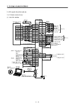
7. Use SW1DNC-MRC2-J. (Refer to section 11.7.) The RS-422 communication function is used with servo amplifiers with
software version A3 or later.
8. Personal computers can also be connected via the CN3 connector, enabling RS-422 communication. Note that using the USB
communication function (CN5 connector) prevents the RS-422 communication function (CN3 connector) from being used, and
vice versa. They cannot be used together.
Personal
computer
RS-232C/RS-422 conversion cable
To RS-232C connector
CN3
Servo amplifier
recommended cable: interface cable
DSV-CABV
(Diatrend)
9. Use an external power supply when inputting a negative voltage.
10. When not using the STO function, attach the short-circuit connector came with a servo amplifier.
11. Configure a circuit to turn off EM2 when the main circuit power is turned off to prevent an unexpected restart of the servo
amplifier.
12 Plus and minus of the power of source interface are the opposite of those of sink interface.
Summary of Contents for MR-J4-100A
Page 9: ...A 8 MEMO ...
Page 61: ...1 FUNCTIONS AND CONFIGURATION 1 44 MEMO ...
Page 67: ...2 INSTALLATION 2 6 MEMO ...
Page 137: ...3 SIGNALS AND WIRING 3 70 MEMO ...
Page 261: ...6 NORMAL GAIN ADJUSTMENT 6 24 MEMO ...
Page 291: ...7 SPECIAL ADJUSTMENT FUNCTIONS 7 30 MEMO ...
Page 299: ...8 TROUBLESHOOTING 8 8 MEMO ...
Page 319: ...9 OUTLINE DRAWINGS 9 20 MEMO ...
Page 461: ...12 ABSOLUTE POSITION DETECTION SYSTEM 12 36 MEMO ...
Page 511: ...14 COMMUNICATION FUNCTION 14 38 MEMO ...
Page 559: ...16 USING A DIRECT DRIVE MOTOR 16 20 MEMO ...
Page 583: ...17 FULLY CLOSED LOOP SYSTEM 17 24 MEMO ...
Page 621: ...APPENDIX App 38 ...
Page 639: ......