


12. ABSOLUTE POSITION DETECTION SYSTEM
12 - 16
12.6 Absolute position data transfer protocol
POINT
After switching on ABSM, turn on SON. When the ABS transfer mode is off,
turning on SON does not switch on the base circuit.
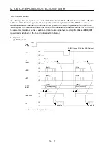
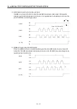
12.6.1 Data transfer procedure
Each time SON is turned on (when the power is switched on for example), the programmable controller
reads the position data (present position) of the servo amplifier.
Time-out monitoring is performed by the programmable controller.
ON (Servo-on) on
Servo amplifier
Programmable controller
ABSM on
ABST on
ABSR on
ABST off
ABSR off
ABST on
ABSR on
ABST off
ABSR off
ABST on
ABSM off
DI0 allocation change
Transmission data set
Transmission data set
DI0 allocation change
Watch dog timer
Reading 2 bits
Shift and addition
Watch dog timer
Reading 2 bits
Shift and addition
Setting the current
position
Sum check
Every time the SON is turned
ON, ABSM is turned ON to set
the data to be transmitted.
The data is read in units of
2 bits; the read data is written
to the lowest bits, and the
register is shifted right until
32-bit data is configured.
The data is read in units of
2 bits; the read data is written
to the lowest bits, and the
register is shifted right until
6-bit data is configured.
A sum check is executed
for the received 32-bit data.
After making sure that
there are no errors in the data,
the current position is set.
Start proce
ssin
g
Re
peat
ed
to
conf
ig
ure
32
-bit
d
a
ta
Repeat
e
d t
o
config
ur
e
6
-bit
da
ta
End
proce
ssin
g
16 times
3 times
«Current position data»
«Sum check data»
ABST off
Summary of Contents for MR-J4-100A
Page 9: ...A 8 MEMO ...
Page 61: ...1 FUNCTIONS AND CONFIGURATION 1 44 MEMO ...
Page 67: ...2 INSTALLATION 2 6 MEMO ...
Page 137: ...3 SIGNALS AND WIRING 3 70 MEMO ...
Page 261: ...6 NORMAL GAIN ADJUSTMENT 6 24 MEMO ...
Page 291: ...7 SPECIAL ADJUSTMENT FUNCTIONS 7 30 MEMO ...
Page 299: ...8 TROUBLESHOOTING 8 8 MEMO ...
Page 319: ...9 OUTLINE DRAWINGS 9 20 MEMO ...
Page 461: ...12 ABSOLUTE POSITION DETECTION SYSTEM 12 36 MEMO ...
Page 511: ...14 COMMUNICATION FUNCTION 14 38 MEMO ...
Page 559: ...16 USING A DIRECT DRIVE MOTOR 16 20 MEMO ...
Page 583: ...17 FULLY CLOSED LOOP SYSTEM 17 24 MEMO ...
Page 621: ...APPENDIX App 38 ...
Page 639: ......