


11. OPTIONS AND AUXILIARY EQUIPMENT
11 - 16
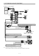
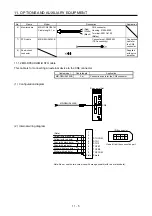
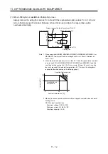
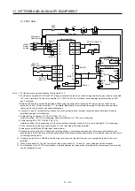
When using cooling fans, install them using the mounting holes provided in the bottom of the
regenerative option.
MR-RB5R/MR-RB9F/MR-RB9T/
MR-RB5K-4/MR-RB6K-4
Mounting screw 4-M3
Top
Bottom
TE1
G4 G3 C P
TE
Cooling fan × 2
(1.0 m
3
/min or more,
92 mm × 92 mm)
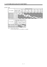
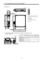
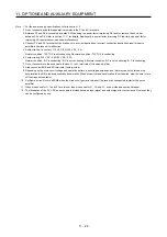
11.2.5 Dimensions
(1) MR-RB12
[Unit: mm]
5
144
Approx. 20
169
168
156
6
12
6
36
40
6 mounting hole
TE1
15
Approx. 6
149
2
TE1 terminal block
G3
G4
P
C
Applicable wire size: 0.2 mm
2
to 2.5 mm
2
(AWG 14 to 12)
Tightening torque: 0.5 to 0.6 [N•m]
Mounting screw
Screw size: M5
Tightening torque: 3.24 [N•m]
Mass: 1.1 [kg]
Summary of Contents for MR-J4-100A
Page 9: ...A 8 MEMO ...
Page 61: ...1 FUNCTIONS AND CONFIGURATION 1 44 MEMO ...
Page 67: ...2 INSTALLATION 2 6 MEMO ...
Page 137: ...3 SIGNALS AND WIRING 3 70 MEMO ...
Page 261: ...6 NORMAL GAIN ADJUSTMENT 6 24 MEMO ...
Page 291: ...7 SPECIAL ADJUSTMENT FUNCTIONS 7 30 MEMO ...
Page 299: ...8 TROUBLESHOOTING 8 8 MEMO ...
Page 319: ...9 OUTLINE DRAWINGS 9 20 MEMO ...
Page 461: ...12 ABSOLUTE POSITION DETECTION SYSTEM 12 36 MEMO ...
Page 511: ...14 COMMUNICATION FUNCTION 14 38 MEMO ...
Page 559: ...16 USING A DIRECT DRIVE MOTOR 16 20 MEMO ...
Page 583: ...17 FULLY CLOSED LOOP SYSTEM 17 24 MEMO ...
Page 621: ...APPENDIX App 38 ...
Page 639: ......