


5. PARAMETERS
5 - 19
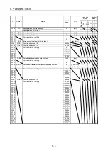
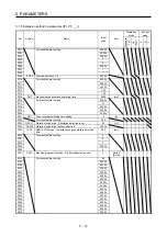
Control
mode
No./symbol/
name
Setting
digit
Function
Initial
value
[unit]
P S T
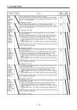
Select the servo motor rotation direction or linear servo motor travel direction for the
input pulse train.
0
Servo motor rotation direction/
linear servo motor travel direction
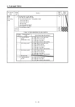
PA14
*POL
Rotation
direction
selection/
travel direction
selection
Setting
value
When forward rotation
pulse is input
When reverse rotation
pulse is input
0
CCW or positive direction CW or negative direction
1
CW or negative direction CCW or positive direction
The following shows the servo motor rotation directions.
Forward rotation (CCW)
Reverse rotation (CW)
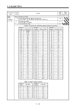
The positive/negative directions of the linear servo motor are as follows.
Secondary side
Primary side
Positive direction
Negative direction
LM-H3/LM-F series
Negative direction
Positive direction
Secondary side
Primary side
LM-U2 series
Negative direction
Positive direction
Table
Primary side
Secondary side
LM-K2 series
Setting range: 0, 1
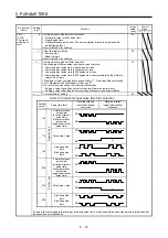
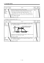
PA15
*ENR
Encoder
output pulses
Set the encoder output pulses from the servo amplifier by using the number of
output pulses per revolution, dividing ratio, or electronic gear ratio. (after
multiplication by 4)
To set a numerator of the electronic gear, select "A-phase/B-phase pulse electronic
gear setting (_ _ 3 _)" of "Encoder output pulse setting selection" in [Pr. PC19].
The maximum output frequency is 4.6 Mpulses/s. Set the parameter within this
range.
Setting range: 1 to 4194304
4000
[pulse/
rev]
PA16
*ENR2
Encoder
output pulses
2
Set a denominator of the electronic gear for the A/B-phase pulse output.
To set a denominator of the electronic gear, select "A-phase/B-phase pulse
electronic gear setting (_ _ 3 _)" of "Encoder output pulse setting selection" in [Pr.
PC19].
Setting range: 1 to 4194304
1
Summary of Contents for MR-J4-100A
Page 9: ...A 8 MEMO ...
Page 61: ...1 FUNCTIONS AND CONFIGURATION 1 44 MEMO ...
Page 67: ...2 INSTALLATION 2 6 MEMO ...
Page 137: ...3 SIGNALS AND WIRING 3 70 MEMO ...
Page 261: ...6 NORMAL GAIN ADJUSTMENT 6 24 MEMO ...
Page 291: ...7 SPECIAL ADJUSTMENT FUNCTIONS 7 30 MEMO ...
Page 299: ...8 TROUBLESHOOTING 8 8 MEMO ...
Page 319: ...9 OUTLINE DRAWINGS 9 20 MEMO ...
Page 461: ...12 ABSOLUTE POSITION DETECTION SYSTEM 12 36 MEMO ...
Page 511: ...14 COMMUNICATION FUNCTION 14 38 MEMO ...
Page 559: ...16 USING A DIRECT DRIVE MOTOR 16 20 MEMO ...
Page 583: ...17 FULLY CLOSED LOOP SYSTEM 17 24 MEMO ...
Page 621: ...APPENDIX App 38 ...
Page 639: ......