


11. OPTIONS AND AUXILIARY EQUIPMENT
11 - 61
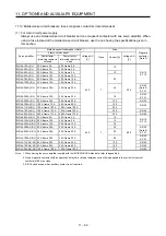
(2) For control circuit power supply
When the wiring for the control circuit power supply (L11, L21) is thinner than that for the main circuit
power supply (L1, L2, L3), install an overcurrent protection device (molded-case circuit breaker or fuse)
to protect the branch circuit.
Molded-case circuit breaker (Note)
Fuse (Class T)
Fuse (Class K5)
Servo amplifier
Frame, rated current
Voltage AC [V]
Current [A]
Voltage AC [V]
Current [A]
Voltage AC [V]
MR-J4-10A(-RJ)
MR-J4-20A(-RJ)
MR-J4-40A(-RJ)
MR-J4-60A(-RJ)
MR-J4-70A(-RJ)
MR-J4-100A(-RJ)
MR-J4-200A(-RJ) 30 A frame 5 A
240
1
300
1
250
MR-J4-350A(-RJ)
MR-J4-500A(-RJ)
MR-J4-700A(-RJ)
MR-J4-11KA(-RJ)
MR-J4-15KA(-RJ)
MR-J4-22KA(-RJ)
MR-J4-60A4(-RJ)
MR-J4-100A4(-RJ)
MR-J4-200A4(-RJ)
MR-J4-350A4(-RJ)
MR-J4-500A4(-RJ) 30 A frame 5 A
480
1
600
1
600
MR-J4-700A4(-RJ)
MR-J4-11KA4(-RJ)
MR-J4-15KA4(-RJ)
MR-J4-22KA4(-RJ)
Note. When having the servo amplifier comply with the IEC/EN/UL/CSA standard, refer to appendix 4.
Summary of Contents for MR-J4-100A
Page 9: ...A 8 MEMO ...
Page 61: ...1 FUNCTIONS AND CONFIGURATION 1 44 MEMO ...
Page 67: ...2 INSTALLATION 2 6 MEMO ...
Page 137: ...3 SIGNALS AND WIRING 3 70 MEMO ...
Page 261: ...6 NORMAL GAIN ADJUSTMENT 6 24 MEMO ...
Page 291: ...7 SPECIAL ADJUSTMENT FUNCTIONS 7 30 MEMO ...
Page 299: ...8 TROUBLESHOOTING 8 8 MEMO ...
Page 319: ...9 OUTLINE DRAWINGS 9 20 MEMO ...
Page 461: ...12 ABSOLUTE POSITION DETECTION SYSTEM 12 36 MEMO ...
Page 511: ...14 COMMUNICATION FUNCTION 14 38 MEMO ...
Page 559: ...16 USING A DIRECT DRIVE MOTOR 16 20 MEMO ...
Page 583: ...17 FULLY CLOSED LOOP SYSTEM 17 24 MEMO ...
Page 621: ...APPENDIX App 38 ...
Page 639: ......