


15. USING A LINEAR SERVO MOTOR
15 - 1
15. USING A LINEAR SERVO MOTOR
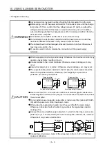
WARNING
When using the linear servo motor, read "Linear Servo Motor Instruction Manual"
and "Linear Encoder Instruction Manual".
POINT
The linear servo system is available for the servo amplifiers of which software
version is A5 or later.
15.1 Functions and configuration
15.1.1 Summary
The fields of semiconductor/LCD manufacturing systems, mounters, and others have strong demands for
high accuracy, high speed, and efficiency. Therefore, the number of systems using a linear servo motor for a
drive axis has been increasing. Since the linear servo system can obtain the characteristics of the high
speed and the high acceleration/deceleration greater than the ball screw drive system. The linear servo
system also does not have a ball screw wear which is a weak point in the ball screw drive system. This will
extend the life of the equipment. In addition, since a response error due to backlash and friction does not
occur, you can establish a high-accuracy system.
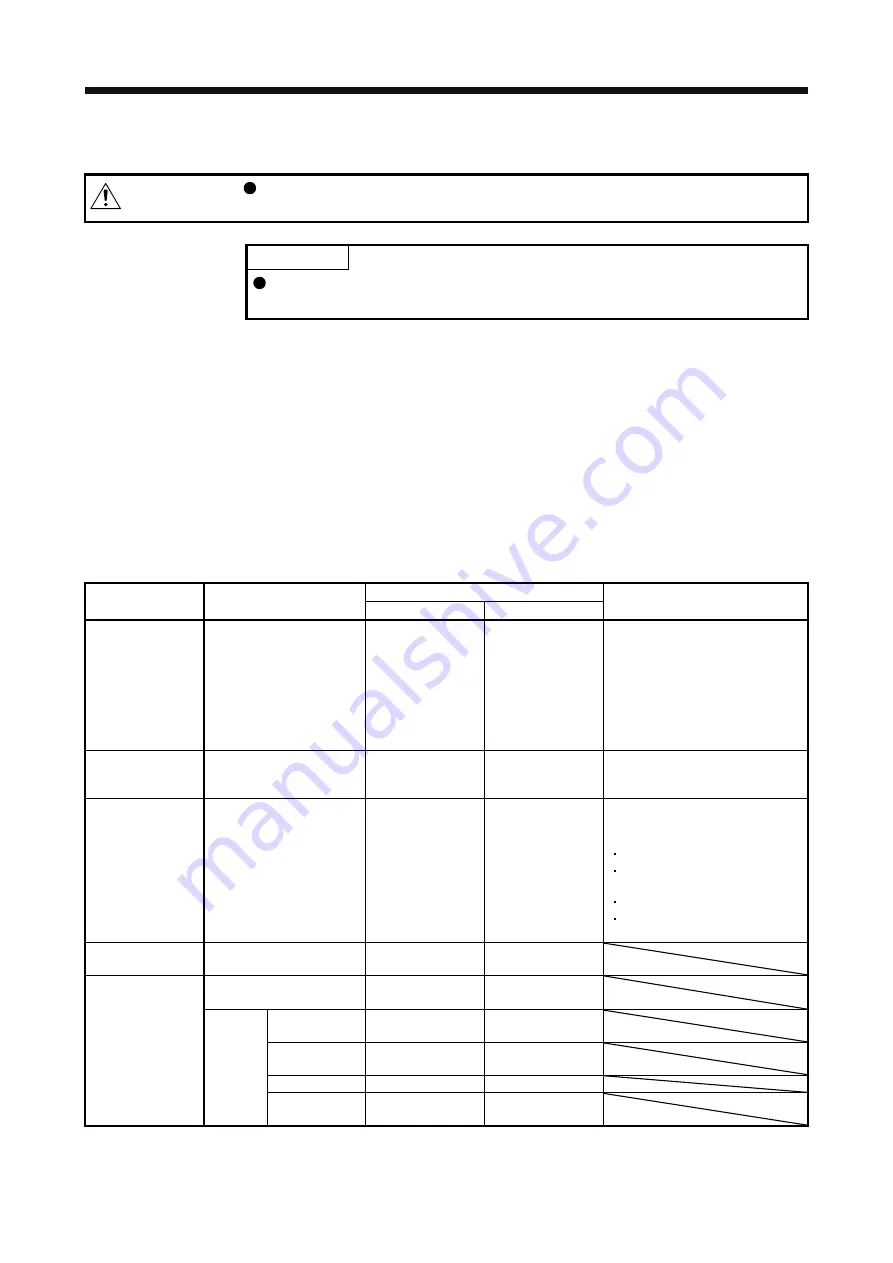
The following shows the differences between the linear servo motor and the rotary servo motor.
Differences
Category Item
Linear servo motor
Rotary servo motor
Remarks
Motor pole
adjustment
Magnetic pole detection
Required
Not required
(default setting)
Automatically executed at the first
servo-on after the power is turned
on.
For the absolute position linear
encoder, [Pr. PL01] can disable the
magnetic pole detection. The timing
of the magnetic pole detection can
be changed with [Pr. PL01]. (Refer
to (2) (b) of section 15.3.3.)
Home position
return
Reference home position
1048576 pulses unit
(initial value)
One servo motor
revolution unit
Home position return pitch can be
changed with parameter setting.
(Refer to section 15.3.3.)
Absolute position
detection system
Absolute position encoder
battery
Not required
Required
The following alarms and warnings
are not provided for the linear servo
motor.
[AL. 25 Absolute position erased]
[AL. 92 Battery cable
disconnection warning]
[AL. 9F Battery warning]
[AL. E3 Absolute position counter
warning]
Auto tuning
Load to motor inertia ratio
(J)
Load to motor mass
ratio
Load to motor
inertia ratio
MR Configurator2
(SW1DNC-MRC2-J)
Motor speed
(Data display and setting)
mm/s unit
r/min unit
Positioning
operation
Supported Supported
(software version
1.19V or later)
Test
operation
function
Motor-less
operation
Not supported
Supported
JOG operation
Not supported
Supported
Program
operation
Supported Supported
Summary of Contents for MR-J4-100A
Page 9: ...A 8 MEMO ...
Page 61: ...1 FUNCTIONS AND CONFIGURATION 1 44 MEMO ...
Page 67: ...2 INSTALLATION 2 6 MEMO ...
Page 137: ...3 SIGNALS AND WIRING 3 70 MEMO ...
Page 261: ...6 NORMAL GAIN ADJUSTMENT 6 24 MEMO ...
Page 291: ...7 SPECIAL ADJUSTMENT FUNCTIONS 7 30 MEMO ...
Page 299: ...8 TROUBLESHOOTING 8 8 MEMO ...
Page 319: ...9 OUTLINE DRAWINGS 9 20 MEMO ...
Page 461: ...12 ABSOLUTE POSITION DETECTION SYSTEM 12 36 MEMO ...
Page 511: ...14 COMMUNICATION FUNCTION 14 38 MEMO ...
Page 559: ...16 USING A DIRECT DRIVE MOTOR 16 20 MEMO ...
Page 583: ...17 FULLY CLOSED LOOP SYSTEM 17 24 MEMO ...
Page 621: ...APPENDIX App 38 ...
Page 639: ......