


13. USING STO FUNCTION
13 - 9
13.3.3 External I/O signal connection example using an external safety relay unit
POINT
This connection is for source interface. For the other I/O signals, refer to the
connection examples in section 3.2.
This connection example complies with the requirement of ISO/EN ISO 13849-1 category 3 PL d.
For details, refer to the safety relay module user’s manual.
S2
K3
KM1
KM1
KM1
KM1
EMG
S4
S3
Safety relay module
MELSEC
(QS90SR2S)
Fuse
24 V
0 V
S1 or
EMG
(Note)
EMG
Control
circuit
Power
supply
S1: STO shut-off switch (STO switch)
S2: Start switch (STO release switch)
S3: On switch
S4: Off switch
KM1: Magnetic contactor
K3: Safety relay
EMG: Emergency stop switch
+24 V
XS0
XS1
Z00 Z10 Z20
X0
COM0
24G
X1
COM1
Z01 Z11 Z21
K3
CN8
CN1
20
EM1
or
EM2
Control circuit
Servo amplifier
STO1
TOFB1
TOFCOM
TOFB2
STO2
STOCOM
M
Servo motor
Note. To enable the STO function of the servo amplifier by using "Emergency switching off", change S1 to EMG. The stop category at
this time is "0". If STO is turned off while the servo motor is rotating, [AL. 63 STO timing error] will occur.
Summary of Contents for MR-J4-100A
Page 9: ...A 8 MEMO ...
Page 61: ...1 FUNCTIONS AND CONFIGURATION 1 44 MEMO ...
Page 67: ...2 INSTALLATION 2 6 MEMO ...
Page 137: ...3 SIGNALS AND WIRING 3 70 MEMO ...
Page 261: ...6 NORMAL GAIN ADJUSTMENT 6 24 MEMO ...
Page 291: ...7 SPECIAL ADJUSTMENT FUNCTIONS 7 30 MEMO ...
Page 299: ...8 TROUBLESHOOTING 8 8 MEMO ...
Page 319: ...9 OUTLINE DRAWINGS 9 20 MEMO ...
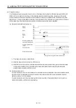
Page 461: ...12 ABSOLUTE POSITION DETECTION SYSTEM 12 36 MEMO ...
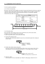
Page 511: ...14 COMMUNICATION FUNCTION 14 38 MEMO ...
Page 559: ...16 USING A DIRECT DRIVE MOTOR 16 20 MEMO ...
Page 583: ...17 FULLY CLOSED LOOP SYSTEM 17 24 MEMO ...
Page 621: ...APPENDIX App 38 ...
Page 639: ......