


3. SIGNALS AND WIRING
3 - 61
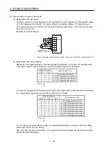
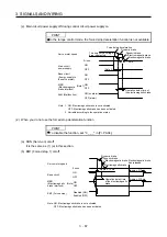
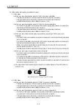
2) Input pulse condition
0.9
0.1
tc
tLH
tc
tHL
tF
PP
NP
tLH = tHL < 0.2 s
tc > 2 s
tF > 3 s
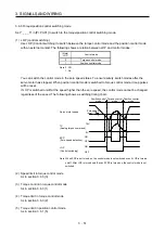
(4) Encoder output pulse DO-2
(a) Open-collector type
Interface
Maximum sink current: 35 mA
Photocoupler
Servo amplifier
OP
LG
SD
Servo amplifier
OP
LG
SD
5 V DC to 24 V DC
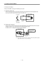
(b) Differential line driver type
1) Interface
Maximum output current: 35 mA
150
Ω
100
Ω
Am26LS32 or equivalent
Servo amplifier
LA
(LB, LZ)
LAR
(LBR, LZR)
SD
LG
High-speed photocoupler
Servo amplifier
LAR
(LBR, LZR)
SD
LA
(LB, LZ)
Summary of Contents for MR-J4-100A
Page 9: ...A 8 MEMO ...
Page 61: ...1 FUNCTIONS AND CONFIGURATION 1 44 MEMO ...
Page 67: ...2 INSTALLATION 2 6 MEMO ...
Page 137: ...3 SIGNALS AND WIRING 3 70 MEMO ...
Page 261: ...6 NORMAL GAIN ADJUSTMENT 6 24 MEMO ...
Page 291: ...7 SPECIAL ADJUSTMENT FUNCTIONS 7 30 MEMO ...
Page 299: ...8 TROUBLESHOOTING 8 8 MEMO ...
Page 319: ...9 OUTLINE DRAWINGS 9 20 MEMO ...
Page 461: ...12 ABSOLUTE POSITION DETECTION SYSTEM 12 36 MEMO ...
Page 511: ...14 COMMUNICATION FUNCTION 14 38 MEMO ...
Page 559: ...16 USING A DIRECT DRIVE MOTOR 16 20 MEMO ...
Page 583: ...17 FULLY CLOSED LOOP SYSTEM 17 24 MEMO ...
Page 621: ...APPENDIX App 38 ...
Page 639: ......