


11. OPTIONS AND AUXILIARY EQUIPMENT
11 - 3
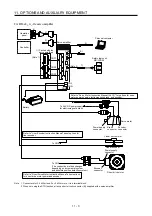
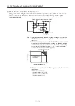
For MR-J4-_A_-RJ servo amplifier
CNP1
CNP2
CNP3
5)
1)
7)
CN9
CN10
MR-J3-D05
2)
3)
4)
CN5
CN6
CN3
CN8
CN1
CN4
CN2L
CN2
6)
Battery
(Packed with the
servo amplifier)
(Note 1)
Personal computer
To 24 V DC power supply
for electromagnetic brake
Servo motor
Encoder
connector
Safety logic unit
Servo amplifier
Operation
panel
Controller
Power supply
connector
Brake
connector
(Note 2)
Refer to "Servo Motor Instruction Manual (Vol. 3)" for options for servo
motor power supply, electromagnetic brake, and encoder.
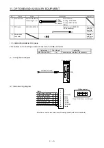
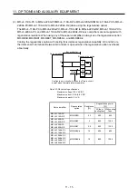
Linear servo motor
Linear encoder
Power supply
connector
Direct drive motor
Encoder
connector
To CN2
(The connection method changes
depending on incremental system
and absolute position detection system.)
Refer to "Liner Encoder Instruction Manual" about options for
liner encoder.
Refer to "Direct Drive Motor Instruction Manual" about options
for direct drive motor power and encoder.
To CN2
Note 1. Connectors for 3.5 kW or less. For 5 kW or more, it is a terminal block.
2. When not using the STO function, attach a short-circuit connector (8)) supplied with a servo amplifier.
Summary of Contents for MR-J4-100A
Page 9: ...A 8 MEMO ...
Page 61: ...1 FUNCTIONS AND CONFIGURATION 1 44 MEMO ...
Page 67: ...2 INSTALLATION 2 6 MEMO ...
Page 137: ...3 SIGNALS AND WIRING 3 70 MEMO ...
Page 261: ...6 NORMAL GAIN ADJUSTMENT 6 24 MEMO ...
Page 291: ...7 SPECIAL ADJUSTMENT FUNCTIONS 7 30 MEMO ...
Page 299: ...8 TROUBLESHOOTING 8 8 MEMO ...
Page 319: ...9 OUTLINE DRAWINGS 9 20 MEMO ...
Page 461: ...12 ABSOLUTE POSITION DETECTION SYSTEM 12 36 MEMO ...
Page 511: ...14 COMMUNICATION FUNCTION 14 38 MEMO ...
Page 559: ...16 USING A DIRECT DRIVE MOTOR 16 20 MEMO ...
Page 583: ...17 FULLY CLOSED LOOP SYSTEM 17 24 MEMO ...
Page 621: ...APPENDIX App 38 ...
Page 639: ......