


15. USING A LINEAR SERVO MOTOR
15 - 21
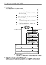
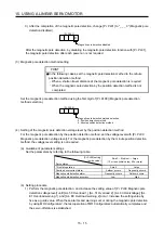
(3) Program operation
Positioning operation can be performed in two or more operation patterns combined, without using a
controller. Use this operation with the forced stop reset. This operation may be used independently of
whether servo-on, servo-off, or whether a controller is connected or not.
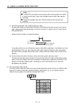
Exercise control on the program operation screen of MR Configurator2. For full information, refer to the
MR Configurator2 Installation Guide.
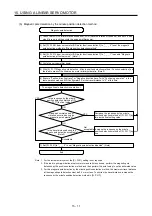
Operation Screen
control
Start
Click the "Operation start" button.
Pause
Click the "Pause" button.
Stop
Click the "Stop" button.
Forced stop
Click the "Forced Stop" button.
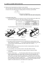
15.3.5 Function
(1) Linear servo control error detection function
POINT
For the linear servo control error detection function, the position and speed
deviation error detections are enabled by default. ([Pr. PL04]: _ _ _ 3)
If the linear servo control gets unstable for some reasons, the linear servo motor may not operate
properly. To detect this state and to stop operation, the linear servo control error detection function is
used as a protective function.
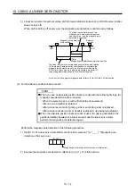
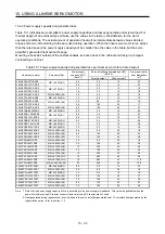
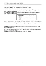
The linear servo control error detection function has three different detection methods: the position
deviation, speed deviation, and thrust deviation. An error is detected when each method is enabled with
[Pr. PL04 Linear servo motor/DD motor function selection 2]. The detection level can be changed with
[Pr. PL05], [Pr. PL06], and [Pr. PL07].
Servo amplifier internal value
1) Model feedback position [mm]
3) Model feedback speed [mm/s]
5) Command thrust [%]
Linear encoder
2) Feedback position [mm]
4) Feedback speed [mm/s]
6) Feedback thrust [%]
Servo amplifier
Linear servo motor
Linear encoder
Figure 15.1 Outline of linear servo control error detection function
Summary of Contents for MR-J4-100A
Page 9: ...A 8 MEMO ...
Page 61: ...1 FUNCTIONS AND CONFIGURATION 1 44 MEMO ...
Page 67: ...2 INSTALLATION 2 6 MEMO ...
Page 137: ...3 SIGNALS AND WIRING 3 70 MEMO ...
Page 261: ...6 NORMAL GAIN ADJUSTMENT 6 24 MEMO ...
Page 291: ...7 SPECIAL ADJUSTMENT FUNCTIONS 7 30 MEMO ...
Page 299: ...8 TROUBLESHOOTING 8 8 MEMO ...
Page 319: ...9 OUTLINE DRAWINGS 9 20 MEMO ...
Page 461: ...12 ABSOLUTE POSITION DETECTION SYSTEM 12 36 MEMO ...
Page 511: ...14 COMMUNICATION FUNCTION 14 38 MEMO ...
Page 559: ...16 USING A DIRECT DRIVE MOTOR 16 20 MEMO ...
Page 583: ...17 FULLY CLOSED LOOP SYSTEM 17 24 MEMO ...
Page 621: ...APPENDIX App 38 ...
Page 639: ......