


11. OPTIONS AND AUXILIARY EQUIPMENT
11 - 5
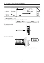
No. Name
Model
Description
Application
6) Monitor
cable
MR-J3CN6CBL1M
Cable length: 1 m
3 (Red)
2 (White)
1 (Black)
CN6 connector
Housing: 51004-0300
Terminal: 50011-8100
(Molex)
7) STO cable
MR-D05UDL3M-B
Connector set: 2069250-1
(TE Connectivity)
Connection
cable for
the CN8
connector
8) Short-circuit
connector
Supplied
with servo
amplifier
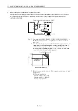
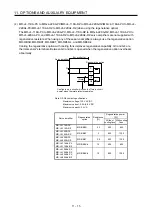
11.1.2 MR-D05UDL3M-B STO cable
This cable is for connecting an external device to the CN8 connector.
Cable model
Cable length
Application
MR-D05UDL3M-B 3
m Connection
cable for the CN8 connector
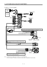
(1) Configuration diagram
Servo amplifier
MR-D05UDL3M-B
CN8
(2) Internal wiring diagram
1
2
3
6
7
Plate
STO2
TOFB1
TOFB2
Shield
STO1
TOFCOM
8
4
5
STOCOM
Yellow (with black dots)
Yellow (with red dots)
Gray (with black dots)
Gray (with red dots)
White (with black dots)
White (with red dots)
(Note)
2
1
6
4
8
CN8 connector
3
5
7
Viewed from the connection part
Note. Do not use the two core wires with orange sheath (with red or black dots).
Summary of Contents for MR-J4-100A
Page 9: ...A 8 MEMO ...
Page 61: ...1 FUNCTIONS AND CONFIGURATION 1 44 MEMO ...
Page 67: ...2 INSTALLATION 2 6 MEMO ...
Page 137: ...3 SIGNALS AND WIRING 3 70 MEMO ...
Page 261: ...6 NORMAL GAIN ADJUSTMENT 6 24 MEMO ...
Page 291: ...7 SPECIAL ADJUSTMENT FUNCTIONS 7 30 MEMO ...
Page 299: ...8 TROUBLESHOOTING 8 8 MEMO ...
Page 319: ...9 OUTLINE DRAWINGS 9 20 MEMO ...
Page 461: ...12 ABSOLUTE POSITION DETECTION SYSTEM 12 36 MEMO ...
Page 511: ...14 COMMUNICATION FUNCTION 14 38 MEMO ...
Page 559: ...16 USING A DIRECT DRIVE MOTOR 16 20 MEMO ...
Page 583: ...17 FULLY CLOSED LOOP SYSTEM 17 24 MEMO ...
Page 621: ...APPENDIX App 38 ...
Page 639: ......