


5. PARAMETERS
5 - 25
Control
mode
No./symbol/
name
Setting
digit
Function
Initial
value
[unit]
P S T
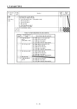
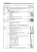
PB09
VG2
Speed loop
gain
Set the gain of the speed loop.
Set this parameter when vibration occurs on machines of low rigidity or large
backlash. Increasing the setting value will also increase the response level but will
be liable to generate vibration and/or noise.
The setting of the parameter will be the automatic setting or manual setting
depending on the [Pr. PA08] setting. Refer to the table of [Pr. PB08] for details.
Setting range: 20 to 65535
823
[rad/s]
PB10
VIC
Speed
integral
compensation
Set the integral time constant of the speed loop.
Decreasing the setting value will increase the response level but will be liable to
generate vibration and/or noise.
The setting of the parameter will be the automatic setting or manual setting
depending on the [Pr. PA08] setting. Refer to the table of [Pr. PB08] for details.
Setting range: 0.1 to 1000.0
33.7
[ms]
PB11
VDC
Speed
differential
compensation
Set the differential compensation.
To enable the setting value, turn on PC (proportional control).
Setting range: 0 to 1000
980
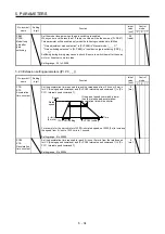
PB12
OVA
Overshoot
amount
compensation
Set a percentage of viscous friction torque against the servo motor rated value or
thrust against the linear servo motor rated value.
When the response level is low or when the torque/thrust is limited, the efficiency of
the parameter may be lower.
Setting range: 0 to 100
0
[%]
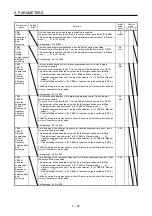
PB13
NH1
Machine
resonance
suppression
filter 1
Machine resonance suppression filter 1
Set the notch frequency of the machine resonance suppression filter 1.
When "Automatic setting (_ _ _ 1)" of "Filter tuning mode selection" is selected with
[Pr. PB01], this parameter will be set automatically.
When "Filter tuning mode selection" is "Manual setting (_ _ _ 2)" in [Pr. PB01], the
setting value is enabled.
Setting range: 10 to 4500
4500
[Hz]
Set the shape of the machine resonance suppression filter 1.
When "Filter tuning mode selection" is "Automatic setting (_ _ _ 1)" in [Pr. PB01], this parameter will be set
automatically.
Set manually for the manual setting.
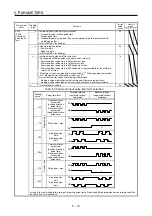
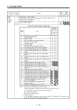
PB14
NHQ1
Notch shape
selection 1
_ _ _ x For manufacturer setting
0h
_ _ x _ Notch depth selection
0: -40 dB
1: -14 dB
2: -8 dB
3: -4 dB
0h
_ x _ _ Notch width selection
0:
α
= 2
1:
α
= 3
2:
α
= 4
3:
α
= 5
0h
x _ _ _ For manufacturer setting
0h
PB15
NH2
Machine
resonance
suppression
filter 2
Set the notch frequency of the machine resonance suppression filter 2.
To enable the setting value, set "Machine resonance suppression filter 2 selection"
to "Enabled (_ _ _ 1)" in [Pr. PB16].
Setting range: 10 to 4500
4500
[Hz]
Summary of Contents for MR-J4-100A
Page 9: ...A 8 MEMO ...
Page 61: ...1 FUNCTIONS AND CONFIGURATION 1 44 MEMO ...
Page 67: ...2 INSTALLATION 2 6 MEMO ...
Page 137: ...3 SIGNALS AND WIRING 3 70 MEMO ...
Page 261: ...6 NORMAL GAIN ADJUSTMENT 6 24 MEMO ...
Page 291: ...7 SPECIAL ADJUSTMENT FUNCTIONS 7 30 MEMO ...
Page 299: ...8 TROUBLESHOOTING 8 8 MEMO ...
Page 319: ...9 OUTLINE DRAWINGS 9 20 MEMO ...
Page 461: ...12 ABSOLUTE POSITION DETECTION SYSTEM 12 36 MEMO ...
Page 511: ...14 COMMUNICATION FUNCTION 14 38 MEMO ...
Page 559: ...16 USING A DIRECT DRIVE MOTOR 16 20 MEMO ...
Page 583: ...17 FULLY CLOSED LOOP SYSTEM 17 24 MEMO ...
Page 621: ...APPENDIX App 38 ...
Page 639: ......