


11. OPTIONS AND AUXILIARY EQUIPMENT
11 - 56
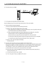
(3) DIMENSIONS
[Unit: mm]
34.8
69.3
38.5
Rating plate
Mass: 66 [g]
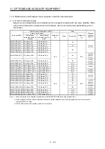
11.9 Selection example of wires
POINT
To comply with the IEC/EN/UL/CSA standard, use the wires shown in appendix
4 for wiring. To comply with other standards, use a wire that is complied with
each standard.
Selection condition of wire size is as follows.
Construction condition: Single wire set in midair
Wire length: 30 m or less
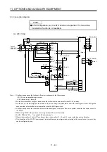
The following diagram shows the wires used for wiring. Use the wires given in this section or equivalent.
5) Power regeneration converter lead
Power regeneration
converter
N-
3) Regenerative option lead
Regenerative option
2) Control circuit power supply lead
C
P+
L1
L2
L3
L11
L21
1) Main circuit power supply lead
Power supply
Servo amplifier
U
V
W
M
4) Servo motor power supply lead
Summary of Contents for MR-J4-100A
Page 9: ...A 8 MEMO ...
Page 61: ...1 FUNCTIONS AND CONFIGURATION 1 44 MEMO ...
Page 67: ...2 INSTALLATION 2 6 MEMO ...
Page 137: ...3 SIGNALS AND WIRING 3 70 MEMO ...
Page 261: ...6 NORMAL GAIN ADJUSTMENT 6 24 MEMO ...
Page 291: ...7 SPECIAL ADJUSTMENT FUNCTIONS 7 30 MEMO ...
Page 299: ...8 TROUBLESHOOTING 8 8 MEMO ...
Page 319: ...9 OUTLINE DRAWINGS 9 20 MEMO ...
Page 461: ...12 ABSOLUTE POSITION DETECTION SYSTEM 12 36 MEMO ...
Page 511: ...14 COMMUNICATION FUNCTION 14 38 MEMO ...
Page 559: ...16 USING A DIRECT DRIVE MOTOR 16 20 MEMO ...
Page 583: ...17 FULLY CLOSED LOOP SYSTEM 17 24 MEMO ...
Page 621: ...APPENDIX App 38 ...
Page 639: ......