


12. ABSOLUTE POSITION DETECTION SYSTEM
12 - 12
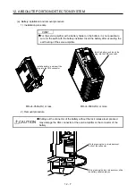
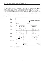
3) Disconnect the connector for servo amplifier connection (orange) of the old MR-BAT6V1BJ
battery for junction battery cable.
When the control circuit power supply is on, performing 3) without [AL. 9F.1 Low battery] will
trigger [AL. 9F.1].
MR-BT6VCBL03M
CN4
CN2
Servo amplifier
Old MR-BAT6V1BJ
New MR-BAT6V1BJ
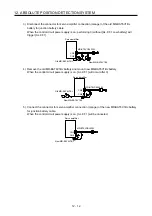
4) Remove the old MR-BAT6V1BJ battery and mount new MR-BAT6V1BJ battery.
When the control circuit power supply is on, [AL. 9F.1] will occur after 3).
MR-BT6VCBL03M
CN4
CN2
Servo amplifier
New MR-BAT6V1BJ
Old MR-BAT6V1BJ
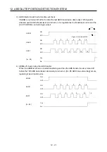
5) Connect the connector for servo amplifier connection (orange) of the new MR-BAT6V1BJ battery
for junction battery cable.
When the control circuit power supply is on, [AL. 9F.1] will be canceled.
MR-BT6VCBL03M
CN4
CN2
Servo amplifier
New MR-BAT6V1BJ
Summary of Contents for MR-J4-100A
Page 9: ...A 8 MEMO ...
Page 61: ...1 FUNCTIONS AND CONFIGURATION 1 44 MEMO ...
Page 67: ...2 INSTALLATION 2 6 MEMO ...
Page 137: ...3 SIGNALS AND WIRING 3 70 MEMO ...
Page 261: ...6 NORMAL GAIN ADJUSTMENT 6 24 MEMO ...
Page 291: ...7 SPECIAL ADJUSTMENT FUNCTIONS 7 30 MEMO ...
Page 299: ...8 TROUBLESHOOTING 8 8 MEMO ...
Page 319: ...9 OUTLINE DRAWINGS 9 20 MEMO ...
Page 461: ...12 ABSOLUTE POSITION DETECTION SYSTEM 12 36 MEMO ...
Page 511: ...14 COMMUNICATION FUNCTION 14 38 MEMO ...
Page 559: ...16 USING A DIRECT DRIVE MOTOR 16 20 MEMO ...
Page 583: ...17 FULLY CLOSED LOOP SYSTEM 17 24 MEMO ...
Page 621: ...APPENDIX App 38 ...
Page 639: ......