


9 OUTLINE DRAWINGS
9 - 13
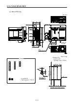
(c) MR-J4-350A4(-RJ)
[Unit: mm]
105
93
6
6
7.5
235
200
6
Approx. 80
Approx. 28
2-
φ
6 mounting hole
Lock knob
250
7.5
6
CNP1
CNP2
CNP3
Cooling fan exhaust
Approx. 73.5
Approx. 69.3
Approx.
38.5
Intake
With
MR-BAT6V1SET
Approx.
34
Mass: 3.6 [kg]
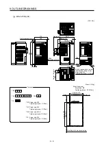
L2
N-
P3
L11
L21
P4
L3
L1
C
D
P+
PE
Terminal
CNP1
CNP2
V
W
U
CNP3
Screw size: M4
Tightening torque: 1.2 [N•m]
Mounting screw
Screw size: M5
Tightening torque: 3.24 [N•m]
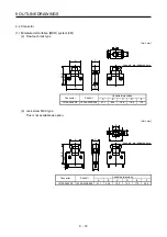
235 ± 0.5
93 ± 0.5
Approx. 6
Approx. 6
A
ppr
ox.
7.5
4-M5 screw
Approx. 105
Approx. 250
Mounting hole process drawing
A
ppr
ox
.
7.5
Summary of Contents for MR-J4-100A
Page 9: ...A 8 MEMO ...
Page 61: ...1 FUNCTIONS AND CONFIGURATION 1 44 MEMO ...
Page 67: ...2 INSTALLATION 2 6 MEMO ...
Page 137: ...3 SIGNALS AND WIRING 3 70 MEMO ...
Page 261: ...6 NORMAL GAIN ADJUSTMENT 6 24 MEMO ...
Page 291: ...7 SPECIAL ADJUSTMENT FUNCTIONS 7 30 MEMO ...
Page 299: ...8 TROUBLESHOOTING 8 8 MEMO ...
Page 319: ...9 OUTLINE DRAWINGS 9 20 MEMO ...
Page 461: ...12 ABSOLUTE POSITION DETECTION SYSTEM 12 36 MEMO ...
Page 511: ...14 COMMUNICATION FUNCTION 14 38 MEMO ...
Page 559: ...16 USING A DIRECT DRIVE MOTOR 16 20 MEMO ...
Page 583: ...17 FULLY CLOSED LOOP SYSTEM 17 24 MEMO ...
Page 621: ...APPENDIX App 38 ...
Page 639: ......