


7. SPECIAL ADJUSTMENT FUNCTIONS
7 - 17
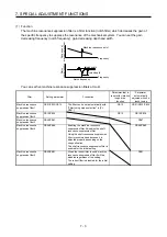
7.2.3 Parameter
When using the gain switching function, always select "Manual mode (_ _ _ 3)" of "Gain adjustment mode
selection" in [Pr. PA08 Auto tuning mode]. The gain switching function cannot be used in the auto tuning
mode.
(1) Variable gain operation setting parameter
Parameter Symbol
Name
Unit
Description
PB26
CDP
Gain switching selection
Used to select the changing condition.
PB27
CDL
Gain switching condition
[kpulse/s]
/[pulse]
/[r/min]
Used to set the changing condition values.
PB28
CDT
Gain switching time constant
[ms]
You can set the filter time constant for a gain change at
changing.
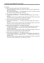
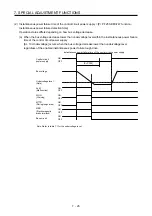
(a) [Pr. PB26 Gain switching function]
Used to set the gain switching condition. Select the switching condition in the first digit and second
digit.
Gain switching selection
0: Disabled
1: Input device (gain switching (CDP))
2: Command frequency
3: Droop pulses
4: Servo motor speed
0 0
Gain switching condition
0: Gain after switching is enabled with gain switching condition or more
1: Gain after switching is enabled with gain switching condition or less
[Pr. PB26]
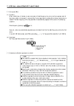
(b) [Pr. PB27 Gain switching condition]
Set a level to switch gains after you select "Command frequency", "Droop pulses", or "Servo motor
speed" in [Pr. PB26 Gain switching function].
The setting unit is as follows.
Gain switching condition
Unit
Command frequency
[kpulse/s]
Droop pulses
[pulse]
Servo motor speed
[r/min]
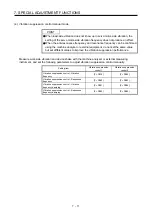
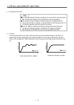
(c) [Pr. PB28 Gain switching time constant]
You can set the primary delay filter to each gain at gain switching. This parameter is used to
suppress shock given to the machine if the gain difference is large at gain switching, for example.
Summary of Contents for MR-J4-100A
Page 9: ...A 8 MEMO ...
Page 61: ...1 FUNCTIONS AND CONFIGURATION 1 44 MEMO ...
Page 67: ...2 INSTALLATION 2 6 MEMO ...
Page 137: ...3 SIGNALS AND WIRING 3 70 MEMO ...
Page 261: ...6 NORMAL GAIN ADJUSTMENT 6 24 MEMO ...
Page 291: ...7 SPECIAL ADJUSTMENT FUNCTIONS 7 30 MEMO ...
Page 299: ...8 TROUBLESHOOTING 8 8 MEMO ...
Page 319: ...9 OUTLINE DRAWINGS 9 20 MEMO ...
Page 461: ...12 ABSOLUTE POSITION DETECTION SYSTEM 12 36 MEMO ...
Page 511: ...14 COMMUNICATION FUNCTION 14 38 MEMO ...
Page 559: ...16 USING A DIRECT DRIVE MOTOR 16 20 MEMO ...
Page 583: ...17 FULLY CLOSED LOOP SYSTEM 17 24 MEMO ...
Page 621: ...APPENDIX App 38 ...
Page 639: ......