


14. COMMUNICATION FUNCTION
14 - 10
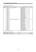
14.4 Command and data No. list
POINT
Even if a command or data No. is the same between different model servo
amplifiers, its description may differ.
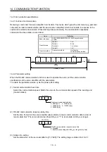
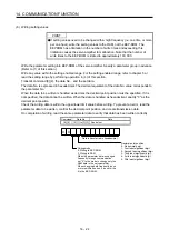
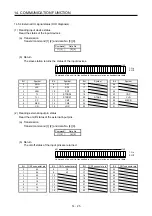
14.4.1 Reading command
(1) Status display (command [0] [1])
Command
Data No.
Description
Status display
Frame
length
[0] [1]
[0] [0]
Status display symbol and unit
Cumulative feedback pulses
Motor-side cumu. feedback pulses (after gear)
16
[0] [1]
Servo motor speed
Servo motor speed
[0] [2]
Droop pulses
Motor-side droop pulses
[0] [3]
Cumulative command pulses
[0] [4]
Command pulse frequency
[0] [5]
Analog speed command voltage
Analog speed limit voltage
[0] [6]
Analog torque limit voltage
Analog torque command voltage
[0] [7]
Regenerative load ratio
[0] [8]
Effective load ratio
[0] [9]
Peak load ratio
[0] [A]
Instantaneous torque
Instantaneous thrust
[0] [B]
Position within one-revolution
Motor encoder position within one-revolution
Virtual position within one-revolution
[0] [C]
ABS counter
Motor encoder ABS counter
Virtual ABS counter
[0] [D]
Load to motor inertia ratio
Load to motor mass ratio
[0] [E]
Bus voltage
[0] [F]
Load-side cumulative feedback pulses
[1] [0]
Load-side droop pulses
[1] [1]
Load-side encoder information 1
Z-phase counter
[1] [2]
Load-side encoder information 2
[1] [6]
Temperature of motor thermistor
[1] [7]
Motor-side cumu. feedback pulses (before gear)
[1] [8]
Electrical angle
[1]
[E]
Motor-side/load-side position deviation
[1]
[F]
Motor-side/load-side speed deviation
[2] [0]
Encoder inside temperature
[2] [1]
Settling time
[2] [2]
Oscillation detection frequency
[2] [3]
Number of tough operations
[2] [8]
Unit power consumption
[2] [9]
Unit total power consumption
Summary of Contents for MR-J4-100A
Page 9: ...A 8 MEMO ...
Page 61: ...1 FUNCTIONS AND CONFIGURATION 1 44 MEMO ...
Page 67: ...2 INSTALLATION 2 6 MEMO ...
Page 137: ...3 SIGNALS AND WIRING 3 70 MEMO ...
Page 261: ...6 NORMAL GAIN ADJUSTMENT 6 24 MEMO ...
Page 291: ...7 SPECIAL ADJUSTMENT FUNCTIONS 7 30 MEMO ...
Page 299: ...8 TROUBLESHOOTING 8 8 MEMO ...
Page 319: ...9 OUTLINE DRAWINGS 9 20 MEMO ...
Page 461: ...12 ABSOLUTE POSITION DETECTION SYSTEM 12 36 MEMO ...
Page 511: ...14 COMMUNICATION FUNCTION 14 38 MEMO ...
Page 559: ...16 USING A DIRECT DRIVE MOTOR 16 20 MEMO ...
Page 583: ...17 FULLY CLOSED LOOP SYSTEM 17 24 MEMO ...
Page 621: ...APPENDIX App 38 ...
Page 639: ......