


13. USING STO FUNCTION
13 - 4
13.1.6 Maintenance
This servo amplifier has alarms and warnings for maintenance that supports the Mitsubishi drive safety
function. (Refer to chapter 8.)
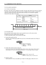
13.2 STO I/O signal connector (CN8) and signal layouts
13.2.1 Signal layouts
POINT
The pin configurations of the connectors are as viewed from the cable connector
wiring section.
TOFB2
STO2
TOFB1
STO1
STOCOM
2
CN8
STO I/O signal connector
Servo amplifier
1
4
3
6
5
8
7
TOFCOM
Summary of Contents for MR-J4-100A
Page 9: ...A 8 MEMO ...
Page 61: ...1 FUNCTIONS AND CONFIGURATION 1 44 MEMO ...
Page 67: ...2 INSTALLATION 2 6 MEMO ...
Page 137: ...3 SIGNALS AND WIRING 3 70 MEMO ...
Page 261: ...6 NORMAL GAIN ADJUSTMENT 6 24 MEMO ...
Page 291: ...7 SPECIAL ADJUSTMENT FUNCTIONS 7 30 MEMO ...
Page 299: ...8 TROUBLESHOOTING 8 8 MEMO ...
Page 319: ...9 OUTLINE DRAWINGS 9 20 MEMO ...
Page 461: ...12 ABSOLUTE POSITION DETECTION SYSTEM 12 36 MEMO ...
Page 511: ...14 COMMUNICATION FUNCTION 14 38 MEMO ...
Page 559: ...16 USING A DIRECT DRIVE MOTOR 16 20 MEMO ...
Page 583: ...17 FULLY CLOSED LOOP SYSTEM 17 24 MEMO ...
Page 621: ...APPENDIX App 38 ...
Page 639: ......