


10. CHARACTERISTICS
10 - 5
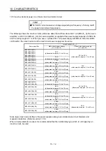
(Note 2) Servo amplifier-generated heat [W]
Servo amplifier
Servo motor
(Note 1)
Power supply
capacity
[kVA]
At rated output
At rated output
[Generated heat
in the cabinet
when cooled
outside the
cabinet] (Note 3)
With servo-off
Area required for
heat dissipation
[m
2
]
HG-JR903 13
435
130
45
8.7
MR-J4-11KA(-RJ)
HG-JR11K1M 16 530 160 45 11.0
MR-J4-15KA(-RJ) HG-JR15K1M
22
640
195
45
13.0
MR-J4-22KA(-RJ) HG-JR22K1M
33
850
260
55
17.0
HG-SR524 1.0
40
18
0.8
MR-J4-60A4(-RJ)
HG-JR534 1.0
40
18
0.8
HG-SR1024
1.7
60
18
1.2
MR-J4-100A4(-RJ) HG-JR734
1.3
60
18
1.2
HG-JR1034
1.7
60
18
1.2
HG-SR1524
2.5
90
20
1.8
HG-SR2024 3.5
90
20 1.8
MR-J4-200A4(-RJ)
HG-JR1534 2.5
90
20
1.8
HG-JR2034
3.5
90
20
1.8
HG-SR3524 5.5
130
20 2.6
MR-J4-350A4(-RJ)
HG-JR3534 5.5
160
20
2.7
HG-SR5024 7.5
195
25 3.9
MR-J4-500A4(-RJ)
HG-JR5034 7.5
195
25
3.9
HG-SR7024 10
300
25 6.0
MR-J4-700A4(-RJ)
HG-JR7034 10
300
25 6.0
HG-JR9034 13
435
130
45
8.7
MR-J4-11KA4(-RJ)
HG-JR11K1M4 16 530 160 45 11.0
MR-J4-15KA4(-RJ) HG-JR15K1M4
22
640
195
45
13.0
MR-J4-22KA4(-RJ) HG-JR22K1M4
33
850
260
55
17.0
Note 1. Note that the power supply capacity will vary according to the power supply impedance. This value is applicable when the
power factor improving AC reactor or power factor improving DC reactor are not used.
2. Heat generated during regeneration is not included in the servo amplifier-generated heat. To calculate heat generated by the
regenerative option, refer to section 11.2.
3. This value is applicable when the servo amplifier is cooled by using the heat sink outside mounting attachment.
Summary of Contents for MR-J4-100A
Page 9: ...A 8 MEMO ...
Page 61: ...1 FUNCTIONS AND CONFIGURATION 1 44 MEMO ...
Page 67: ...2 INSTALLATION 2 6 MEMO ...
Page 137: ...3 SIGNALS AND WIRING 3 70 MEMO ...
Page 261: ...6 NORMAL GAIN ADJUSTMENT 6 24 MEMO ...
Page 291: ...7 SPECIAL ADJUSTMENT FUNCTIONS 7 30 MEMO ...
Page 299: ...8 TROUBLESHOOTING 8 8 MEMO ...
Page 319: ...9 OUTLINE DRAWINGS 9 20 MEMO ...
Page 461: ...12 ABSOLUTE POSITION DETECTION SYSTEM 12 36 MEMO ...
Page 511: ...14 COMMUNICATION FUNCTION 14 38 MEMO ...
Page 559: ...16 USING A DIRECT DRIVE MOTOR 16 20 MEMO ...
Page 583: ...17 FULLY CLOSED LOOP SYSTEM 17 24 MEMO ...
Page 621: ...APPENDIX App 38 ...
Page 639: ......