


5. PARAMETERS
5 - 41
Control
mode
No./symbol/
name
Setting
digit
Function
Initial
value
[unit]
P S T
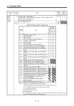
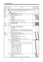
PC24
*COP3
Function
selection C-3
_ _ _ x In-position range unit selection
Select a unit of in-position range.
0: Command input pulse unit
1: Servo motor encoder pulse unit
0h
_ _ x _ For manufacturer setting
0h
_ x _ _
0h
x _ _ _ Error excessive alarm level unit selection
Select a setting unit of the error excessive alarm level set in [Pr. PC43].
0: Per 1 rev or 1 mm
1: Per 0.1 rev or 0.1 mm
2: Per 0.01 rev or 0.01 mm
3: Per 0.001 rev or 0.001 mm
0h
PC26
*COP5
Function
selection C-5
_ _ _ x [AL. 99 Stroke limit warning] selection
Select [AL. 99 Stroke limit warning].
0: Enabled
1: Disabled
0h
_ _ x _ For manufacturer setting
0h
_ x _ _
0h
x _ _ _
0h
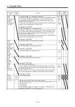
PC27
*COP6
Function
selection C-6
_ _ _ x [AL. 10 Undervoltage] detection method selection
Set this parameter when [AL. 10 undervoltage] occurs due to power supply voltage
distortion while using FR-RC-(H) or FR-CV-(H).
0: When [AL. 10] does not occur
1: When [AL. 10] occurs
0h
_ _ x _ For manufacturer setting
0h
_ x _ _
0h
x _ _ _
0h
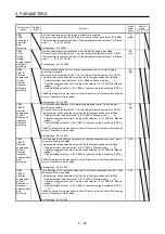
PC30
STA2
Acceleration
time constant
2
To enable the parameter, turn on STAB2 (Speed acceleration/deceleration
selection).
Set the acceleration time required to reach the rated speed from 0 r/min or 0 mm/s
for VC (Analog speed command) and [Pr. PC05 Internal speed command 1] to [Pr.
PC11 Internal speed command 7].
Setting range: 0 to 50000
0
[ms]
PC31
STB2
Deceleration
time constant
2
To enable the parameter, turn on STAB2 (Speed acceleration/deceleration
selection).
Set the deceleration time required to reach 0 r/min or 0 mm/s from the rated speed
for VC (Analog speed command) and [Pr. PC05 Internal speed command 1] to [Pr.
PC11 Internal speed command 7].
Setting range: 0 to 50000
0
[ms]
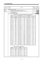
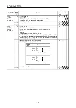
PC32
CMX2
Commanded
pulse
multiplication
numerator 2
To enable the parameter, select "Electronic gear (0 _ _ _)" or "J3A electronic gear
setting value compatibility mode (2 _ _ _)" of "Electronic gear selection" in [Pr.
PA21].
Setting range: 1 to 16777215
1
PC33
CMX3
Commanded
pulse
multiplication
numerator 3
To enable the parameter, select "Electronic gear (0 _ _ _)" or "J3A electronic gear
setting value compatibility mode (2 _ _ _)" of "Electronic gear selection" in [Pr.
PA21].
Setting range: 1 to 16777215
1
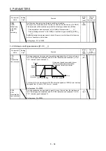
PC34
CMX4
Commanded
pulse
multiplication
numerator 4
To enable the parameter, select "Electronic gear (0 _ _ _)" or "J3A electronic gear
setting value compatibility mode (2 _ _ _)" of "Electronic gear selection" in [Pr.
PA21].
Setting range: 1 to 16777215
1
PC35
TL2
Internal
torque limit 2
Set the parameter on the assumption that the maximum torque or thrust is 100.0%.
The parameter is for limiting the torque of the servo motor or the thrust of the linear
servo motor.
No torque or thrust is generated when this parameter is set to "0.0".
When TL1 (Internal torque limit selection) is turned on, Internal torque limits 1 and 2
are compared and the lower value will be enabled.
Setting range: 0.0 to 100.0
100.0
[%]
Summary of Contents for MR-J4-100A
Page 9: ...A 8 MEMO ...
Page 61: ...1 FUNCTIONS AND CONFIGURATION 1 44 MEMO ...
Page 67: ...2 INSTALLATION 2 6 MEMO ...
Page 137: ...3 SIGNALS AND WIRING 3 70 MEMO ...
Page 261: ...6 NORMAL GAIN ADJUSTMENT 6 24 MEMO ...
Page 291: ...7 SPECIAL ADJUSTMENT FUNCTIONS 7 30 MEMO ...
Page 299: ...8 TROUBLESHOOTING 8 8 MEMO ...
Page 319: ...9 OUTLINE DRAWINGS 9 20 MEMO ...
Page 461: ...12 ABSOLUTE POSITION DETECTION SYSTEM 12 36 MEMO ...
Page 511: ...14 COMMUNICATION FUNCTION 14 38 MEMO ...
Page 559: ...16 USING A DIRECT DRIVE MOTOR 16 20 MEMO ...
Page 583: ...17 FULLY CLOSED LOOP SYSTEM 17 24 MEMO ...
Page 621: ...APPENDIX App 38 ...
Page 639: ......