


11. OPTIONS AND AUXILIARY EQUIPMENT
11 - 34
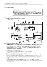
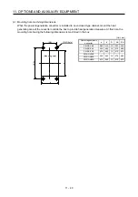
(2) FR-BR-(H) Resistor unit
[Unit: mm]
H3 ± 1
H1 ± 3
Approx.
H2
Approx.
H2
D1
H ± 5
2-
φ
C
Control circuit
terminal
Main circuit
terminal
W1 ± 1
Approx. 35
Approx. 35
C
C
W ± 5
D ± 5
(Note)
(Note)
Note. Ventilation ports are provided on both sides and the top. The bottom is open.
Resistor
unit
W W1 H H1 H2 H3 D D1 C
Approximate
mass [kg]
FR-BR-15K 170
100
450
410
20
432
220
3.2
6
15
FR-BR-30K 340
270
600
560
20
582
220
4 10
30
200 V
class
FR-BR-55K 480
410
700
620
40
670
450
3.2
12
70
FR-BR-H30K 340
270
600
560
20
582
220 4 10
30
400 V
class
FR-BR-H55K 480
410
700
620
40
670
450
3.2 12
70
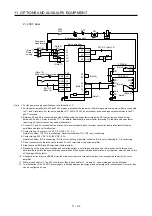
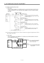
(3) MT-BR5-(H) resistor unit
[Unit: mm]
Resistor unit
Resistance
Approximate
mass [kg]
200 V
class
MT-BR5-55K 2.0
Ω
50
400 V
class
MT-BR5-H75K 6.5
Ω
70
4
φ
15 mounting hole
300
75
75
450
7.5
7.5
M6
M4
193
189
480
510
85
85
800
37
60
21
10
40
30
NP
Summary of Contents for MR-J4-100A
Page 9: ...A 8 MEMO ...
Page 61: ...1 FUNCTIONS AND CONFIGURATION 1 44 MEMO ...
Page 67: ...2 INSTALLATION 2 6 MEMO ...
Page 137: ...3 SIGNALS AND WIRING 3 70 MEMO ...
Page 261: ...6 NORMAL GAIN ADJUSTMENT 6 24 MEMO ...
Page 291: ...7 SPECIAL ADJUSTMENT FUNCTIONS 7 30 MEMO ...
Page 299: ...8 TROUBLESHOOTING 8 8 MEMO ...
Page 319: ...9 OUTLINE DRAWINGS 9 20 MEMO ...
Page 461: ...12 ABSOLUTE POSITION DETECTION SYSTEM 12 36 MEMO ...
Page 511: ...14 COMMUNICATION FUNCTION 14 38 MEMO ...
Page 559: ...16 USING A DIRECT DRIVE MOTOR 16 20 MEMO ...
Page 583: ...17 FULLY CLOSED LOOP SYSTEM 17 24 MEMO ...
Page 621: ...APPENDIX App 38 ...
Page 639: ......