


17. FULLY CLOSED LOOP SYSTEM
17 - 4
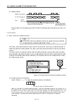
17.1.3 System configuration
(1) For a linear encoder
(a) MR-J4-_A_ servo amplifier
CN2
Table
(Note)
Two-wire type serial interface
compatible linear encoder
Load-side encoder signal
Servo motor encoder signal
Linear encoder head
Servo motor
Servo amplifier
Controller
Note. Applicable for the absolute position detection system when an absolute position linear encoder is used.
In that case, a battery is not required.
(b) MR-J4-_A_-RJ servo amplifier
(Note)
A/B/Z-phase pulse train interface compatible
linear encoder or two-wire/four-wire type serial
interface compatible linear encoder
Load-side encoder signal
CN2L
(A/B/Z-phase pulse train interface
or serial interface)
CN2
Table
Servo motor encoder signal
Linear encoder head
Servo motor
Servo amplifier
Controller
Note. Applicable for the absolute position detection system when an absolute position linear encoder is used.
In that case, a battery is not required.
Summary of Contents for MR-J4-100A
Page 9: ...A 8 MEMO ...
Page 61: ...1 FUNCTIONS AND CONFIGURATION 1 44 MEMO ...
Page 67: ...2 INSTALLATION 2 6 MEMO ...
Page 137: ...3 SIGNALS AND WIRING 3 70 MEMO ...
Page 261: ...6 NORMAL GAIN ADJUSTMENT 6 24 MEMO ...
Page 291: ...7 SPECIAL ADJUSTMENT FUNCTIONS 7 30 MEMO ...
Page 299: ...8 TROUBLESHOOTING 8 8 MEMO ...
Page 319: ...9 OUTLINE DRAWINGS 9 20 MEMO ...
Page 461: ...12 ABSOLUTE POSITION DETECTION SYSTEM 12 36 MEMO ...
Page 511: ...14 COMMUNICATION FUNCTION 14 38 MEMO ...
Page 559: ...16 USING A DIRECT DRIVE MOTOR 16 20 MEMO ...
Page 583: ...17 FULLY CLOSED LOOP SYSTEM 17 24 MEMO ...
Page 621: ...APPENDIX App 38 ...
Page 639: ......