


7. SPECIAL ADJUSTMENT FUNCTIONS
7 - 28
7.4 Compliance with SEMI-F47 standard
POINT
The control circuit power supply of the servo amplifier can comply with SEMI-
F47. However, a back-up capacitor may be necessary for instantaneous power
failure in the main circuit power supply depending on the power supply
impedance and operating situation. Be sure to check them by testing the entire
equipment using actual machines.
Use a 3-phase for the input power supply of the servo amplifier.
The following explains the compliance with "SEMI-F47 semiconductor process equipment voltage sag
immunity test" of MR-J4 series.
(1) Parameter setting
Setting [Pr. PA20] and [Pr. PF25] as follows will enable SEMI-F47.
Parameter
Setting
value
Description
PA20
_ 1 _ _ SEMI-F47 selection
PF25 200
Set the time [ms] of the [AL. 10.1 Voltage drop in the control circuit power]
occurrence.
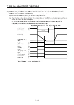
Enabling SEMI-F47 will change operation as follows.
(a) The voltage will drop in the control circuit power at "Rated voltage × 50% or less". After 200 ms, [AL.
10.1 Voltage drop in the control circuit power] will occur.
(b) [AL. 10.2 Voltage drop in the main circuit power] will occur when bus voltage is as follows.
Table 7.1 Voltages which trigger [AL. 10.2 Voltage drop in the main circuit power]
Servo amplifier
Bus voltage which triggers alarm
MR-J4-10A(-RJ)
to
MR-J4-700A(-RJ)
158 V DC
MR-J4-11KA(-RJ)
to
MR-J4-22KA(-RJ)
200 V DC
MR-J4-60A4(-RJ)
to
MR-J4-22KA4(-RJ)
380 V DC
(c) MBR (Electromagnetic brake interlock) will turn off when [AL. 10.1 Voltage drop in the control circuit
power] occurs.
(2) Requirements conditions of SEMI-F47 standard
Table 7.2 shows the permissible time of instantaneous power failure for instantaneous power failure of
SEMI-F47 standard.
Table 7.2 Requirements conditions of SEMI-F47 standard
Instantaneous power
failure voltage
Permissible time of
instantaneous power
failure [s]
Rated voltage × 80%
1
Rated voltage × 70%
0.5
Rated voltage × 50%
0.2
Summary of Contents for MR-J4-100A
Page 9: ...A 8 MEMO ...
Page 61: ...1 FUNCTIONS AND CONFIGURATION 1 44 MEMO ...
Page 67: ...2 INSTALLATION 2 6 MEMO ...
Page 137: ...3 SIGNALS AND WIRING 3 70 MEMO ...
Page 261: ...6 NORMAL GAIN ADJUSTMENT 6 24 MEMO ...
Page 291: ...7 SPECIAL ADJUSTMENT FUNCTIONS 7 30 MEMO ...
Page 299: ...8 TROUBLESHOOTING 8 8 MEMO ...
Page 319: ...9 OUTLINE DRAWINGS 9 20 MEMO ...
Page 461: ...12 ABSOLUTE POSITION DETECTION SYSTEM 12 36 MEMO ...
Page 511: ...14 COMMUNICATION FUNCTION 14 38 MEMO ...
Page 559: ...16 USING A DIRECT DRIVE MOTOR 16 20 MEMO ...
Page 583: ...17 FULLY CLOSED LOOP SYSTEM 17 24 MEMO ...
Page 621: ...APPENDIX App 38 ...
Page 639: ......