


11. OPTIONS AND AUXILIARY EQUIPMENT
11 - 59
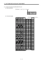
(2) Selection example of crimp terminals
(a) 200 V class
Servo amplifier-side crimp terminals
Applicable tool
Symbol
(Note 2)
Crimp terminal
Body Head Dice
Manufacturer
a FVD5.5-4
YNT-1210S
b (Note 1) 8-4NS
YHT-8S
c FVD2-4
d FVD2-M3
YNT-1614
e FVD1.25-M3 YNT-2216
f FVD14-6
YF-1
YNE-38
DH-122
DH-112
g FVD5.5-6
YNT-1210S
h FVD22-6
YF-1
YNE-38
DH-123
DH-113
i FVD38-8
YF-1
YNE-38
DH-124
DH-114
j FVD5.5-8
YNT-1210S
k FVD8-6
YF-1/E-4
YNE-38
DH-121
DH-111
JST
Note 1. Coat the crimping part with an insulation tube.
2. Some crimp terminals may not be mounted depending on the size. Make sure to use the
recommended ones or equivalent ones.
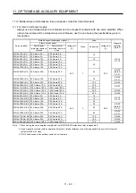
(b) 400 V class
Servo amplifier-side crimp terminals
Applicable
tool
Symbol
Crimp terminal
(Note)
Body Head Dice
Manufacturer
a FVD5.5-4
YNT-1210S
b FVD2-4
c FVD2-M3
YNT-1614
d FVD5.5-6
YNT-1210S
e FVD5.5-8
YNT-1210S
f FVD2-6
YNT-1614
g FVD8-6
h FVD8-8
DH-121/DH-111
i FVD14-8
YF-1 YNE-38
DH-122/DH-112
JST
Note. Some crimp terminals may not be mounted depending on the size. Make sure to use the
recommended ones or equivalent ones.
Summary of Contents for MR-J4-100A
Page 9: ...A 8 MEMO ...
Page 61: ...1 FUNCTIONS AND CONFIGURATION 1 44 MEMO ...
Page 67: ...2 INSTALLATION 2 6 MEMO ...
Page 137: ...3 SIGNALS AND WIRING 3 70 MEMO ...
Page 261: ...6 NORMAL GAIN ADJUSTMENT 6 24 MEMO ...
Page 291: ...7 SPECIAL ADJUSTMENT FUNCTIONS 7 30 MEMO ...
Page 299: ...8 TROUBLESHOOTING 8 8 MEMO ...
Page 319: ...9 OUTLINE DRAWINGS 9 20 MEMO ...
Page 461: ...12 ABSOLUTE POSITION DETECTION SYSTEM 12 36 MEMO ...
Page 511: ...14 COMMUNICATION FUNCTION 14 38 MEMO ...
Page 559: ...16 USING A DIRECT DRIVE MOTOR 16 20 MEMO ...
Page 583: ...17 FULLY CLOSED LOOP SYSTEM 17 24 MEMO ...
Page 621: ...APPENDIX App 38 ...
Page 639: ......