


12. ABSOLUTE POSITION DETECTION SYSTEM
12 - 33
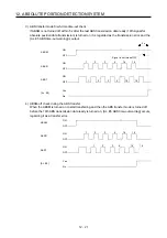
(2) Transfer method
The following shows a sequence how to turn on the base circuit while it is off state because SON is off,
EM2 is off, or an alarm is occurring. In the absolute position detection system, always give the serial
communication command to read the current position in the servo amplifier to the controller every time
RD turns on. The servo amplifier sends the current position to the controller on receipt of the command.
At the same time, this data is set as a position command value in the servo amplifier.
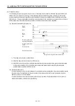
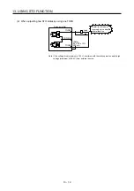
(a) Sequence processing at power-on
OFF
95 ms
ON
OFF
ON
OFF
ON
OFF
ON
5 ms
Power
supply
Base
circuit
Absolute position data
command transmission
Absolute position data
receive
Current position
Pulse train command
Current position change
During this period, get absolute position data.
SON
RD
Absolute position
data
1) The base circuit turns on after 95 ms.
2) After the base circuit is turned on, RD turns on.
3) After RD turned on and the controller acquired the absolute position data, give command pulses
to the servo amplifier. If the controller gives command pulses before acquiring the absolute
position data, a position shift can occur.
(b) Communication error
If a communication error occurs between the controller and servo amplifier, the servo amplifier sends
the error code. The definition of the error code is the same as that of the communication function.
Refer to section 14.3.3 for details.
If a communication error has occurred, perform retry operation. If several retries do not result in a
normal termination, perform error processing.
Summary of Contents for MR-J4-100A
Page 9: ...A 8 MEMO ...
Page 61: ...1 FUNCTIONS AND CONFIGURATION 1 44 MEMO ...
Page 67: ...2 INSTALLATION 2 6 MEMO ...
Page 137: ...3 SIGNALS AND WIRING 3 70 MEMO ...
Page 261: ...6 NORMAL GAIN ADJUSTMENT 6 24 MEMO ...
Page 291: ...7 SPECIAL ADJUSTMENT FUNCTIONS 7 30 MEMO ...
Page 299: ...8 TROUBLESHOOTING 8 8 MEMO ...
Page 319: ...9 OUTLINE DRAWINGS 9 20 MEMO ...
Page 461: ...12 ABSOLUTE POSITION DETECTION SYSTEM 12 36 MEMO ...
Page 511: ...14 COMMUNICATION FUNCTION 14 38 MEMO ...
Page 559: ...16 USING A DIRECT DRIVE MOTOR 16 20 MEMO ...
Page 583: ...17 FULLY CLOSED LOOP SYSTEM 17 24 MEMO ...
Page 621: ...APPENDIX App 38 ...
Page 639: ......