


Chapter 5: Installation
Installing the Processing Server (PS-1)
Inter-Tel
®
5000 Installation Manual – Issue 2.4, May 2008
Page 5-53
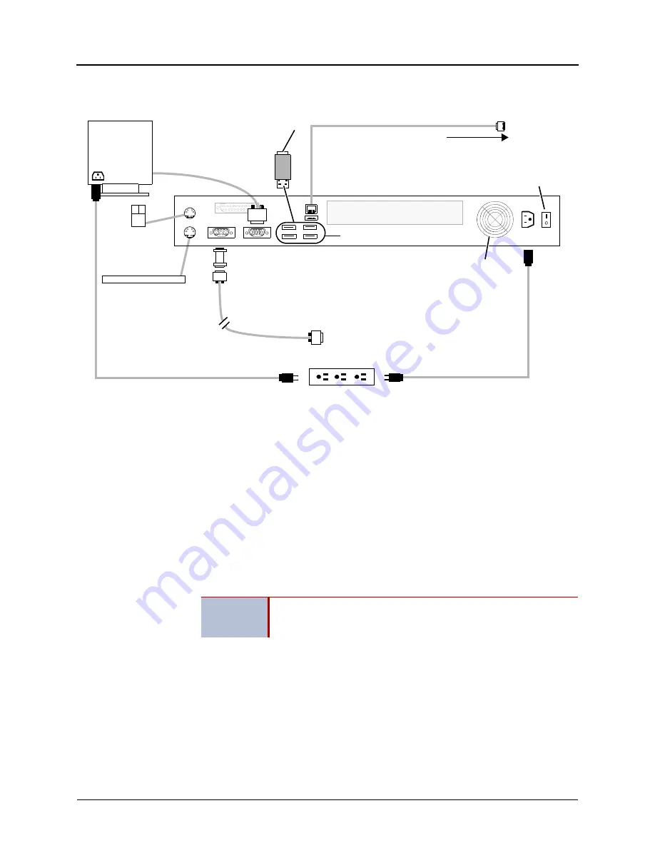
Figure 5-27
shows the back of PS-1 units.
Figure 5-27.
Processing Server (PS-1) Chassis, Back View
Installing the Processing Server (PS-1)
To see the location of connectors on the PS-1, see Figure 5-26 on
page 5-52
and
Figure 5-27
.
To install a PS-1:
1.
Rack mount the PS-1 (recommended).
2.
Make sure the power switches on the front and back of the PS-1 are turned off. See
Figures 5-26 and Figure 5-27 on
page 5-53
.
3.
Connect the PS-1 to an AC power source, but do not turn either of the power switches
on at this time. For electrical requirements, see Table 4-13 on
page 4-31
.
4.
Using a CAT5 or CAT5e cable terminated on both ends with RJ-45 plugs, connect the
PS-1 to the network through the same 100 Mbps LAN switch as the Base Server.
5.
Connect a monitor and keyboard to the PS-1. See
Figure 5-27
. If a monitor and
keyboard are not available, you can use a laptop PC equipped with a DB-9 serial port. In
the alternate mode using a laptop PC, connect the PS-1 to the laptop with a straight-
through RS-232 cable and null modem with hardware flow control, as shown in
Figure 5-
27
.
6.
Turn power on using the On/Off switch on the back of the chassis. Leave the On/Off
switch on the back of the chassis turned on at all times.
7.
Turn power on using the button switch on the front of the chassis. Use the button switch
to control power to the system. Leave the On/Off switch on the back of the chassis
turned on at all times.
Isolated, dedicated, single-phase commercial power source
Monitor
DB-15
Keyboard
Mouse
Power
Switch
(not included)
(optional)
Fan
or
RS-232 cable
DB9M to DB9F Straight-through
On/Off
Null modem
VGA
Connection
to monitor
with Hardware Flow Control (Part no. 804.2605)
(Part no. 813.1683)
RJ-45 to LAN
Connect to Laptop PC
PS-1
power cord
Monitor
power cord
USB Security Key
(Insert in any
USB port.)
USB ports
IMPORTANT
The PS-1 and Base Server must be connected to the network on the
same LAN, VLAN, and subnet. For additional details, see “Network
Environment Requirements” on
page 5-146
.
Summary of Contents for Inter-Tel 5000
Page 1: ...Inter Tel 5000 M I T E L Installation and Maintenance Manual ...
Page 2: ......
Page 3: ...Issue 2 4 May 2008 Inter Tel 5000 Installation and Maintenance Manual Part Number 580 8000 ...
Page 4: ......
Page 6: ......
Page 20: ......
Page 62: ......
Page 366: ......
Page 432: ......
Page 467: ......
Page 468: ...Part No 580 8000 Issue 2 4 May 2008 A691 9111A ...


