


UART Modules
Freescale Semiconductor
32-26
32.5.1
Interrupt and DMA Request Initialization
32.5.1.1
Setting up the UART to Generate Core Interrupts
The list below provides steps to properly initialize the UART to generate an interrupt request to the
processor’s interrupt controller. See
Section 17.2.9.1, “Interrupt Sources,”
for details on interrupt
assignments for the UART modules.
1. Initialize the appropriate ICR
x
register in the interrupt controller.
2. Unmask appropriate bits in IMR in the interrupt controller.
3. Unmask appropriate bits in the core’s status register (SR) to enable interrupts.
4. If TXRDY or RXRDY generates interrupt requests, verify that the corresponding UART DMA
channels are not enabled.
5. Initialize interrupts in the UART, see
.
32.5.1.2
Setting up the UART to Request DMA Service
The UART is capable of generating two internal DMA request signals: transmit and receive.
The transmit DMA request signal is asserted when the TXRDY (transmitter ready) in the UART interrupt
status register (UISR
n
[TXRDY]) is set. When the transmit DMA request signal is asserted, the DMA can
initiate a data copy, reading the next character transmitted from memory and writing it into the UART
transmit buffer (UTB
n
). This allows the DMA channel to stream data from memory to the UART for
transmission without processor intervention. After the entire message has been moved into the UART, the
DMA would typically generate an end-of-data-transfer interrupt request to the CPU. The resulting
interrupt service routine (ISR) could query the UART programming model to determine the
end-of-transmission status.
Similarly, the receive DMA request signal is asserted when the FIFO full or receive ready
(FFULL/RXRDY) flag in the interrupt status register (UISR
n
[FFULL/RXRDY]) is set. When the receive
DMA request signal is asserted, the DMA can initiate a data move, reading the appropriate characters from
the UART receive buffer (URB
n
) and storing them in memory. This allows the DMA channel to stream
data from the UART receive buffer into memory without processor intervention. After the entire message
has been moved from the UART, the DMA would typically generate an end-of-data-transfer interrupt
request to the CPU. The resulting interrupt service routine (ISR) should query the UART programming
model to determine the end-of-transmission status. In typical applications, the receive DMA request
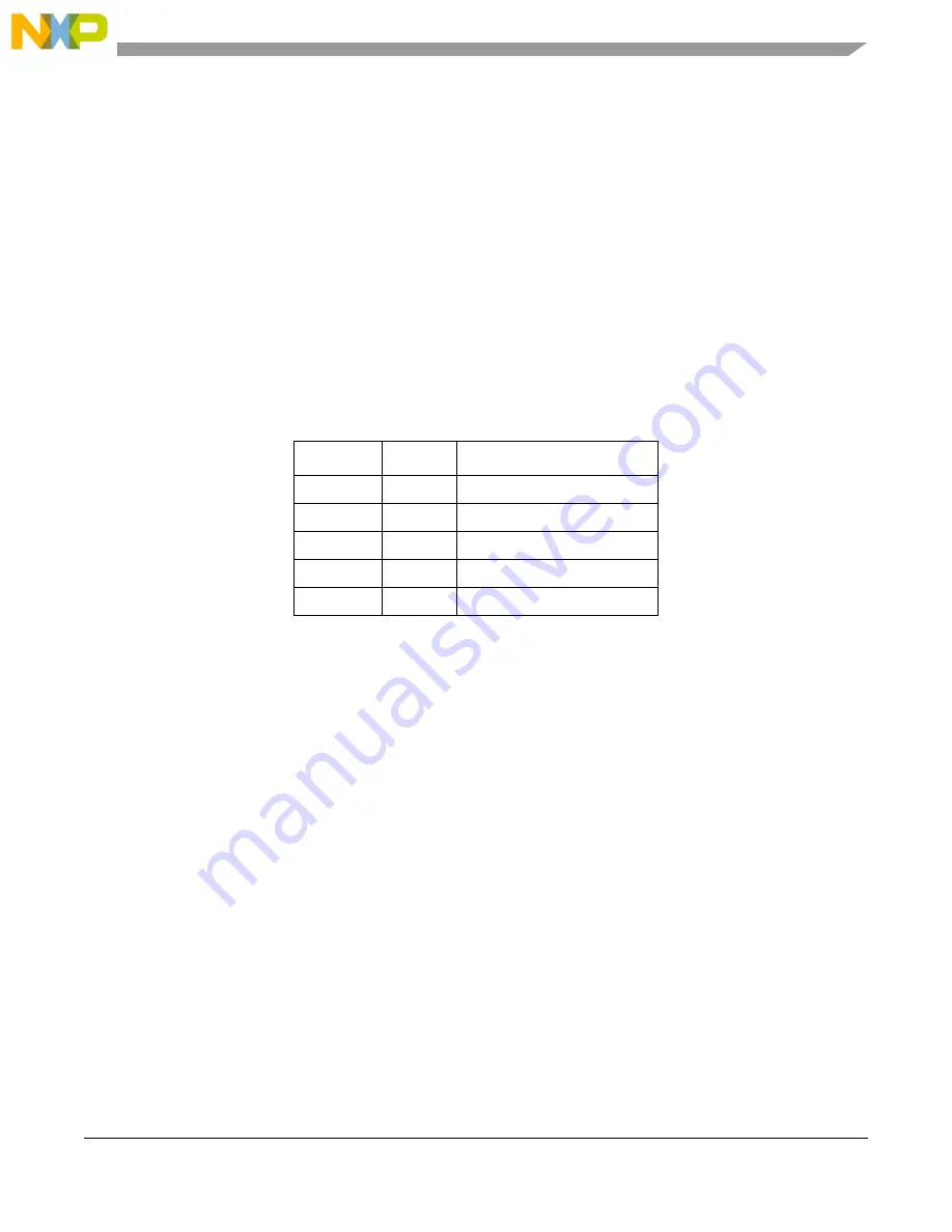
Table 32-13. UART Interrupts
Register
Bit
Interrupt
UMR1
n
6
RxIRQ
UIMR
n
7
Change of State (COS)
UIMR
n
2
Delta Break
UIMR
n
1
RxFIFO Full
UIMR
n
0
TXRDY
Summary of Contents for MCF54455
Page 33: ...xxviii Freescale Semiconductor ...
Page 67: ...Freescale Semiconductor 1 ...
Page 125: ...Freescale Semiconductor 1 ...
Page 145: ...Enhanced Multiply Accumulate Unit EMAC 5 21 Freescale Semiconductor ...
Page 173: ...Cache 6 28 Freescale Semiconductor ...
Page 179: ...Static RAM SRAM 7 6 Freescale Semiconductor ...
Page 207: ...Power Management 9 16 Freescale Semiconductor ...
Page 323: ...Reset Controller Module 13 8 Freescale Semiconductor ...
Page 389: ...Pin Multiplexing and Control 16 44 Freescale Semiconductor ...
Page 575: ...PCI Bus Controller 22 58 Freescale Semiconductor ...
Page 600: ...Advanced Technology Attachment ATA Freescale Semiconductor 23 25 ...
Page 601: ...Freescale Semiconductor 1 ...
Page 842: ...I2 C Interface Freescale Semiconductor 33 16 ...
Page 843: ...Freescale Semiconductor 1 ...
Page 921: ...Revision History A 6 Freescale Semiconductor ...


