


UART Modules
32-21
Freescale Semiconductor
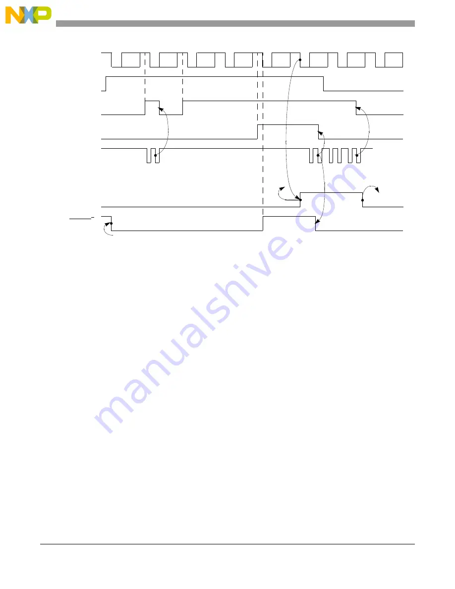
Figure 32-20. Receiver Timing Diagram
32.4.2.3
FIFO
The FIFO is used in the UART’s receive buffer logic. The FIFO consists of three receiver holding registers.
The receive buffer consists of the FIFO and a receiver shift register connected to the U
n
RXD (see
). Data is assembled in the receiver shift register and loaded into the top empty receiver
holding register position of the FIFO. Therefore, data flowing from the receiver to the CPU is
quadruple-buffered.
In addition to the data byte, three status bits—parity error (PE), framing error (FE), and received break
(RB)—are appended to each data character in the FIFO; overrun error (OE) is not appended. By
programming the ERR bit in the UART’s mode register (UMR1
n
), status is provided in character or block
modes.
USR
n
[RXRDY] is set when at least one character is available to be read by the CPU. A read of the receive
buffer produces an output of data from the top of the FIFO. After the read cycle, the data at the top of the
FIFO and its associated status bits are popped and the receiver shift register can add new data at the bottom
of the FIFO. The FIFO-full status bit (FFULL) is set if all three positions are filled with data. The RXRDY
or FFULL bit can be selected to cause an interrupt and TXRDY or RXRDY can be used to generate a DMA
request.
The two error modes are selected by UMR1
n
[ERR]:
•
In character mode (UMR1
n
[ERR] = 0), status is given in the USR
n
for the character at the top of
the FIFO.
C1
C2
C4
C6
C7
C8
C3
C5
C6, C7, and C8 is lost
(C2)
Status
Data
(C3)
Status
Data
(C4)
Status
Data
C5 is
lost
Reset by
command
Receiver
Enabled
USR
n
[RXRDY]
Overrun
Internal
module
select
USR
n
[FFULL]
(C1)
Status
Data
USR
n
[OE]
Automatically asserted
when ready to receive
Manually asserted first time,
automatically negated if overrun occurs
UOP0[RTS] = 1
1
UMR2
n
[RXRTS] = 1
U
n
RXD
U
n
RTS
1
Summary of Contents for MCF54455
Page 33: ...xxviii Freescale Semiconductor ...
Page 67: ...Freescale Semiconductor 1 ...
Page 125: ...Freescale Semiconductor 1 ...
Page 145: ...Enhanced Multiply Accumulate Unit EMAC 5 21 Freescale Semiconductor ...
Page 173: ...Cache 6 28 Freescale Semiconductor ...
Page 179: ...Static RAM SRAM 7 6 Freescale Semiconductor ...
Page 207: ...Power Management 9 16 Freescale Semiconductor ...
Page 323: ...Reset Controller Module 13 8 Freescale Semiconductor ...
Page 389: ...Pin Multiplexing and Control 16 44 Freescale Semiconductor ...
Page 575: ...PCI Bus Controller 22 58 Freescale Semiconductor ...
Page 600: ...Advanced Technology Attachment ATA Freescale Semiconductor 23 25 ...
Page 601: ...Freescale Semiconductor 1 ...
Page 842: ...I2 C Interface Freescale Semiconductor 33 16 ...
Page 843: ...Freescale Semiconductor 1 ...
Page 921: ...Revision History A 6 Freescale Semiconductor ...


