


UART Modules
32-23
Freescale Semiconductor
Because the transmitter is inactive, USR
n
[TXEMP,TXRDY] is inactive and data is sent as it is received.
Received parity is checked but not recalculated for transmission. Character framing is also checked, but
stop bits are sent as they are received. A received break is echoed as received until the next valid start bit
is detected.
32.4.3.2
Local Loopback Mode
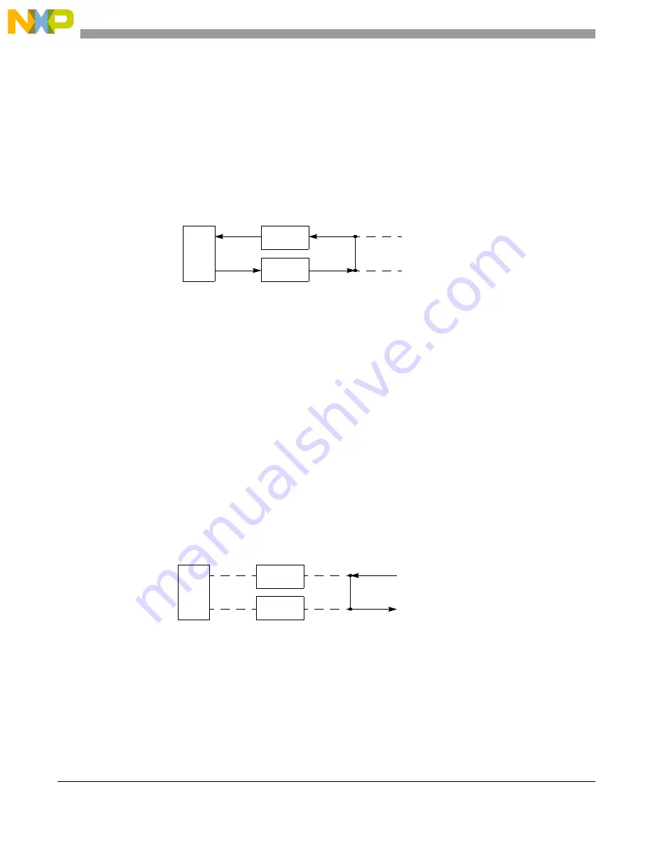
shows how U
n
TXD and U
n
RXD are internally connected in local loopback mode. This
mode is for testing the operation of a UART by sending data to the transmitter and checking data
assembled by the receiver to ensure proper operations.
Figure 32-22. Local Loopback
Features of this local loopback mode are:
•
Transmitter and CPU-to-receiver communications continue normally in this mode.
•
U
n
RXD input data is ignored.
•
U
n
TXD is held marking.
•
The receiver is clocked by the transmitter clock. The transmitter must be enabled, but the receiver
need not be.
32.4.3.3
Remote Loopback Mode
In remote loopback mode, shown in
, the UART automatically transmits received data bit by
bit on the U
n
TXD output. The local CPU-to-transmitter link is disabled. This mode is useful in testing
receiver and transmitter operation of a remote UART. For this mode, transmitter uses the receiver clock.
Because the receiver is not active, received data cannot be read by the CPU and all status conditions are
inactive. Received parity is not checked and is not recalculated for transmission. Stop bits are sent as they
are received. A received break is echoed as received until next valid start bit is detected.
Figure 32-23. Remote Loopback
32.4.4
Multidrop Mode
Setting UMR1
n
[PM] programs the UART to operate in a wake-up mode for multidrop or multiprocessor
applications. In this mode, a master can transmit an address character followed by a block of data
characters targeted for one of up to 256 slave stations.
CPU
Disabled
Disabled
Tx
Rx
U
n
RXD Input
U
n
TXD Output
CPU
Disabled
Disabled
Tx
Rx
Disabled
Disabled
U
n
TXD Output
U
n
RXD Input
Summary of Contents for MCF54455
Page 33: ...xxviii Freescale Semiconductor ...
Page 67: ...Freescale Semiconductor 1 ...
Page 125: ...Freescale Semiconductor 1 ...
Page 145: ...Enhanced Multiply Accumulate Unit EMAC 5 21 Freescale Semiconductor ...
Page 173: ...Cache 6 28 Freescale Semiconductor ...
Page 179: ...Static RAM SRAM 7 6 Freescale Semiconductor ...
Page 207: ...Power Management 9 16 Freescale Semiconductor ...
Page 323: ...Reset Controller Module 13 8 Freescale Semiconductor ...
Page 389: ...Pin Multiplexing and Control 16 44 Freescale Semiconductor ...
Page 575: ...PCI Bus Controller 22 58 Freescale Semiconductor ...
Page 600: ...Advanced Technology Attachment ATA Freescale Semiconductor 23 25 ...
Page 601: ...Freescale Semiconductor 1 ...
Page 842: ...I2 C Interface Freescale Semiconductor 33 16 ...
Page 843: ...Freescale Semiconductor 1 ...
Page 921: ...Revision History A 6 Freescale Semiconductor ...


